The previous chapters illustrated ways to make mechatronic systems produce music autonomously using programs stored on a microcontroller. The creative possibilities of such systems are vast, but their scope widens when the panoply of hardware and software tools designed for music creation is included. To use these tools in concert with our mechatronic inventions, we need to make different systems talk to each other. This form of communication occurs between systems or devices. Another form of communication occurs within a system where some parts (e.g., sensors) provide feedback about some aspect of the system’s state and/or environment (e.g., sound, light, position, etc.), which is used to control other parts of the system (e.g., motor position). This feedback allows a machine to sense its environment, interpret information, choose among possibilities, and take action: this is how a machine becomes a robot. As these abilities are realized, questions of control emerge: What actions are determined before an experience begins? What actions result from interpretations of the experience once started? What aspects are controlled by the human and what are determined by the machine? In what ways can the human(s) and machine(s) interact with each other?
We will start with the question of how to enable communication between devices, so that one, for example, could control a mechatronic percussionist from a typical Digital Audio Workstation (DAW). We will then move on to the world of intra-device communication to see how feedback (sensing—interpreting—acting) can enable new kinds of creative expression.
While it is possible to store musical sequences in a microcontroller’s memory, using a separate computer to generate musical instructions opens up many possibilities (such as working with notation programs and DAWs). To do so, we need to make a computer and a microcontroller talk to each other. This project is a first step toward that goal using serial communication.
- Write a program so that a number is input and printed in the serial monitor.
- Modify the program so that the Arduino’s onboard LED illuminates when the number 7 is input in the serial monitor.
- Write a program that generates a rhythmic sequence and prompts a user to enter a tempo value that governs the rate at which the sequence plays. First, have the rhythm play only using the built-in LED, and then incorporate an actuating system (such as Project 1: Solenoid Percussion).
Same as Project 1: Solenoid Percussion.
Serial communication involves sending or receiving information one bit at a time. It is imperative that both devices connected to a serial bus are configured identically. There are different protocols including SPI, and I2C that establish the rules of such configurations. A UART (universal asynchronous receiver/transmitter) translates information from the numerous parallel data lines and control pins of a microcontroller to the transmit (TX) and receive (RX) pins of the serial interface. A UART makes data packets and transmits them via the TX pin and samples the RX pin to parse incoming data. The baud rate is the speed at which data is transmitted, expressed in bits per second (bps), and must be the same for the sender and receiver.
A serial port is called a communications (COM) port. To see available ports:
- Mac
- open up a terminal window
- type
ls /dev/cu.*orls /dev/tty.*
- Windows
- open Device Manager
- select View / Show hidden devices in the menu bar
- expand the Ports (COM & LPT)
Once you know what ports are available, establish a serial connection through the serial monitor of an Integrated Development Environment (IDE) such as Arduino or Platformio. In Arduino’s editor, the monitor is located in the upper right corner (Figure 4.1):

This interface can be used to transmit and receive values from a program. Only two devices can communicate on one serial bus; ensure that any other devices are disconnected.
Lesson: Common serial communication problems result when
- The serial port is busy because another device is already connected. Disconnect all devices and connect with the ones you want to use.
- Devices are not set to the same baud rate.
Working with a serial monitor via a keyboard involves ASCII, which is a standard for how text is represented in numbers. The following is an abbreviated table that shows the relationship between numerical values and ASCII characters:
| Decimal | Character | Decimal | Character | Decimal | Character |
|---|---|---|---|---|---|
| 0 | null | 42 | * | 65–90 | A–Z |
| 9 | tab | 43 | + | 91 | [ |
| 10 | line feed | 44 | , | 92 | \ |
| 13 | carriage return | 45 | - | 93 | ] |
| 32 | space | 46 | . | 94 | ^ |
| 33 | ! | 47 | / | 95 | _ |
| 34 | “ | 48–57 | 0–9 | 96 | ` |
| 35 | # | 58 | : | 97–122 | a–z |
| 36 | $ | 59 | ; | 123 | { |
| 37 | % | 60 | < | 124 | | |
| 38 | & | 61 | = | 125 | } |
| 39 | ‘ | 62 | > | 126 | ~ |
| 40 | ( | 63 | ? | 127 | delete |
| 41 | ) | 64 | @ |
Communication problems can arise when a value is transmitted in one form and then encoded in another.
Lesson: If unexpected values are produced in the communication process, check to see if there is a translation issue (e.g., involving ASCII).
We will look at specific examples of this in the next section.
To enable serial communication, the following must be included in the program:
Serial.begin()
Opens the serial port; sets the configuration and rate of data transmission in bits/second.
void setup() {
  Serial.begin(9600); // opens serial port, sets data rate to 9600 bps
}
Serial.available()
Returns the number of bytes available to be read.
void loop() {
  if (Serial.available() > 0) {
    // read the incoming byte:
    // do something here
  }
}
The preceding example includes an if statement that allows specified actions to be performed when a condition is met. When paired with an else statement, the commands to run if the conditions are not met can also be specified.
if
Syntax:
if (condition) {
  // if the condition is true, run this statement block;
}
else {
  // if the condition is false, run this statement block;
}
if (i > 7) {
  digitalWrite(LED, HIGH);
}
else {
  digitalWrite(LED, LOW);
}
An alternative to if is the while statement.
while
Syntax:
while (condition) {
  // if the condition is true, run this statement block;
}
while (i > 7) {
  digitalWrite(LED, HIGH);
}
A while statement loops perpetually until the condition becomes false. The difference between an if and a while statement is that a true condition in an if statement will run the bracketed code block and then move to the next statement. When a while statement is true, the enclosed statement block continually loops.
These conditions utilize comparison operators, which include:
| Symbol | Meaning |
|---|---|
== | Equal to |
!= | Not equal to |
< | Less than |
> | Greater than |
<= | Less than or equal to |
>= | Greater than or equal to |
Note that “equal to” (==) is different than the assignment operator (=).
Serial.read()
Returns the first byte of available data (or -1 if no data is available). Calling the function again returns the next available byte of data.
void loop() {
  byte inByte1 = Serial.read(); // read the first byte
  byte inByte2 = Serial.read(); // read the second byte
}
ASCII encoding and Serial.read sometimes result in confusion. Say you write an if() statement with a condition to run a statement block when the number 7 is received. If the ASCII character “7” is entered (say, via a keyboard into the serial monitor), it will be translated to the value 55, which will produce the value FALSE when interpreted by the if() statement. One way to fix this issue is to define the variable that is storing the data from Serial.read as type char, and then use a character in the condition of the if statement:
char inByte1 = Serial.read();
if (inByte1 == '7') {
  //statement;
}
We will look at other ways to convert ASCII characters later in the chapter.
Serial.println()
Prints data to the serial monitor along with carriage return and newline characters.
void loop() {
  Serial.println(inByte1); // print inByte1 to the serial monitor
}
There are other functions that read data from the serial port, such as Serial.parseInt(), Serial.parseFloat(), Serial.readBytes(), and Serial.readBytesUntil(), but these are blocking; as described in Project 6, we want to avoid such commands in the case of music!
Data input into the serial monitor is transmitted one character at a time. If we want to combine characters, such as in a word (“go”) or a number (100), then we need to tell the program when the entire message has been received. One way to do this is to specify what is sent at the end of a line in the serial monitor by clicking the “New Line” dropdown menu (Figure 4.2).

When “New Line” is selected, then a newline character (\n) is added after each entry. Characters can be grouped together in the proper sequence using an array. In the beginning of the program, declare an array of type char with a specified size to store incoming characters:
const byte bufferSize = 8;
char dataReceived[bufferSize];
To count through the array, we will use a variable called index:
static byte index = 0;Check the serial buffer to see if any data is present and if it is, assign it to the variable inByte1:
if (Serial.available() > 0) {
  char inByte1 = Serial.read();
}
See if the incoming data is a Newline character. If it is not, we want to add it to the array at the appropriate index. After the data is added, increment the index for the next addition:
if (inByte1 != '\n') {
  dataReceived[index] = inByte1;
  index++;
}
If the data received is a Newline character (which can be set up either as an else or an if statement), then terminate the string, reset the index (to prepare for the next word or number) and convert the characters in the buffer into integers, which can be used to set the appropriate timing for the sequence (e.g., using delay() or millis() as shown in Chapter 3):
if (inByte1 == '\n') {
  dataReceived[index] = '\0'; // terminate the string
  index = 0;
  tempo = atoi(dataReceived); // convert characters in buffer to integers
}
If you run into problems along the way, use Serial.print() and Serial.println() to show the values that the computer is working with. This leads to the following lesson:
Lesson: Sending and receiving (via printing) data between a computer and a microcontroller using serial communications is a fundamental way to identify and fix problems in your code.
- For goal #1 use both the
Serial.read()andSerial.parseInt()functions. Are there differences in what they return? If so, what explains these differences? - For goal #3 first generate musical sequences using the
delay()function. Write another version of the program that instead uses a non-blocking timer approach (Project 6). Do you notice performance differences between the programs as you enter new tempo values? What explains these differences? - Incorporate a way to start and stop the program by entering commands into the serial monitor (such as “go” and “stop”).
We now have a way for a computer and a microcontroller to exchange data, but entering text and numbers into a serial monitor leaves something to be desired as an interface for musical composition and performance. Instead, we would like to be able to use the many software programs that are specifically designed for musical purposes, such as a DAW or notation program. This project will enable such connections using the Max software environment and the actuation system built in Project 1: Solenoid Percussion.
- Send one-byte messages from a Max patch that activate a solenoid with an ontime specified in the Arduino program.
- Send two-byte messages (note, velocity) that determine when the solenoid turns on and off.
- Connect a DAW such as Ableton Live to the Max patch and the microcontroller. Make a rhythm in a MIDI track that is played by a solenoid.
- Create a short piece in a DAW that is played by an actuator and a sonic object (e.g., a musical instrument). Instead of looping one pattern for the duration of the piece, create different rhythms, tempo changes, and meters.
- Same as Project 1: Solenoid Percussion.
- Serial communication Max for Live Device
- Ableton Live (or other DAW that can send and receive MIDI information)
The code in this example is similar to that developed in Project 8—Using the Serial Monitor—but here it is simpler, since we are sending numbers rather than characters, so we do not need to worry about ASCII encoding.
First, let’s look at where the messages will be sent from: here, a Max patch. Max (cycling74.com) is a graphical programming environment that is flexible, powerful, and widely used by composers, performers, and instrument/interface builders. It is also integrated with Ableton Live via Max for Live, greatly expanding Ableton’s capabilities. In-depth investigations of Max and Ableton are outside the scope of this book (there are many other volumes dedicated to these subjects), but we will look inside the programs to better understand how information is communicated between them. Download the serial communications Max for Live (M4L) device and drag and drop it into an empty MIDI track in Ableton (Figure 4.3).

Clicking the edit button (red arrow above) allows us to look inside the device. The patch opens in a new window where the internal connections can be viewed by turning presentation mode off (View / Presentation). The patch is seen in Figure 4.4.

The Max environment involves objects that perform specified tasks, given their settings and inputs. The flow of the program is described below, where the list numbers correspond to the numbers of the colored boxes (panels) in the patch. The red letters in the patch indicate the position of max objects, which are referred to with brackets in the text below (e.g., [A] in the text refers to the object next to the red letter “A” in Figure 4.4). The names of Max elements are indicated in italics.
- The button object [A] sends out a “bang” (which means “go”) to a trigger object [B] that sends a “clear” message to a popup menu (umenu) [C] and the commands “refresh” and “print” to a serial object [D] (messages are sent right to left out of objects in Max). The “print” message causes the serial object to output the serial ports that are available (both in the Max window, which is opened with the message [E] containing “;”, and out of the right outlet of the serial object), which are selected (route [F]), separated (iter [G]), and prepended (prepend [H]) with the message “append” in order to fill the umenu [C] with available serial ports.
- Another umenu [I] allows a user to select a serial port by letter (e.g., “a”), which is prepended with the message “port” and then sent to the serial object to connect to that port.
- The baud rate, the rate at which serial data is communicated, is input in the number box [J]. This value is output into a message containing the command “baud $1,” where the “$1” is replaced with any number that is input into the message. This message is then sent to the serial object to set the baud rate.
- Transmitting data to an external connection is achieved by sending numbers to the serial object. This can be done via a number box [K], messages [L], or by routing incoming MIDI data via the midiin [M] and midiparse [N] objects.
Turning presentation mode on (View menu or screen icon in the bottom left border of the screen) will then select and organize the interface elements that you see in the Max for Live device.
With a sense of how the host program works and knowledge of its outputs, we can write the Arduino code. Use the same approach as learned in Project 8: establish the serial connection, check to see if there is data in the serial buffer, read that data into a variable, and print it to the serial monitor to see what was received. Test the value received according to a condition (e.g., with if(), switch…case, etc.), which runs other blocks of code. Start by illuminating the built-in LED with one byte at first (goal 1) and then two bytes (goal 2). When working with two bytes, remember that data is processed in sequence. After the first byte is read and assigned to a variable, repeat the process to read and assign the second variable. The conditional statements will then depend on both variables, which can be achieved with statements in sequence or with Boolean Operators such as:
| Symbol | Logic |
|---|---|
&& | and |
! | not |
|| | or |
The following code tests both values to see if they met the specified conditions. If they do, then the statement block is run.
if (inByte1 == 7 && inByte2 > 0) {
  //statement block
}
Refer to the two-byte messages being sent by the Max for Live device when writing these conditional statements in the Arduino code.
With the ability to send two-byte messages from Max to the Arduino, we can engage with MIDI commands from a DAW. The most fundamental MIDI messages are note (pitch) and velocity (volume). Open up the Max for Live device again and take it out of presentation mode. The midiin object [M] transmits MIDI data from Ableton into the Max environment. We are only interested in note and velocity information here, which the midiparse object [N] filters out of its leftmost outlet. These two-value pairs are then sent to the serial object, just as we sent two-value pairs (e.g., 7 100) from the message boxes in the Max for Live device. Make a simple sequence in Ableton and play it: you should see the note and velocity information appear in the message box in the bottom right part of the Max for Live. Include the appropriate Serial.print commands in the Arduino code and open up the serial monitor: you should see the MIDI data from Ableton!
With information flowing from a DAW, we must account for note on and note off messages in the Arduino code. In the MIDI protocol, a note on message starts a note, and a note off message stops it. A note on message consists of a note value from 0 to 127 and a velocity value from 1 to 127. A note off message consists of a note value from 0 to 127 and a velocity value of 0. Each note that you make in your DAW will generate both messages. For example:
84 100 | starts the pitch C5 at a velocity of 100 |
84 0 | stops the pitch C5 |
This information can be used as the basis for the conditional statements in the Arduino code: velocities that are greater than 0 could turn the solenoid on, while velocities of 0 could turn it off. It is then a matter of mapping the appropriate note value to the appropriate microcontroller pin number.
Instead of using the built-in LED, have the sequence activate a pin that is connected to the solenoid circuit from Project 1. You are now using software on a computer to control an actuator: this is a cornerstone of making musical machines.
The preceding is applicable if you are using a DAW other than Ableton Live, but the configuration is different, given that other DAWs do not natively integrate Max patches. In this case, you will work with a standalone version of the Serial Communications patch, which is similar to the Max for Live device we just reviewed. Download and open the max patch (the Max application is available from cycling74.com). The main difference from the previous example is how the two programs will communicate, which here will be via MIDI. Connection between the two environments can be established by specifying the same MIDI port (“to Max 1” here).
- Open the patch in the Max application, go to View / MIDI Setup, and select “to Max 1” in the input section.
- In the patch, double click on the midin object and select “to Max 1” to select that MIDI port.
- In your DAW, select “to Max 1” as the output of your MIDI track (how to do this will vary depending on your DAW).
Play your MIDI track and you should now see the data being transmitted to both the Max patch and the microcontroller!
A common issue when trying to get these systems to talk to each other is that a serial port is busy, preventing connections. This leads to a lesson that can save you time and frustration:
Lesson: If data is not getting from Max to the Arduino:
- Disconnect the Serial Monitor in your IDE.
- Refresh the port list in Max and select the appropriate serial port.
- Start the serial connection in the IDE.
Stopping, resetting, and starting systematically can fix a panoply of technological problems.
The system described often creates mismatches between MIDI note numbers, which correspond to pitches, and the numbers associated with microcontroller pins. In Ableton, C4 corresponds to MIDI note 72. You can’t use this number to directly write to a pin on most microcontrollers because there are not 72 pins on the board. If you want MIDI notes to directly control pins without any translation in the code, specify the range starting at C-2 (MIDI note 0). For an unpitched percussion instrument, this is not usually a problem in a DAW (other than having to scroll down to the bottom of the piano roll, whose default view is usually around C4) because the lack of a clear pitch makes the MIDI note mappings arbitrary. A pitched instrument is more problematic. If you have a string instrument with a range from C4 to C5, we would like (or need) to write in the actual range of the instrument. In the case of software that is based on traditional staff notation, these scenarios are problematic as conventional clefs do not naturally accommodate notations in the range starting at C-2. An alternative is to write within the instrument’s actual range and then use a transposing MIDI effect (e.g., MIDI Effects / Pitch in Ableton, or a Max for Live device) to map the appropriate range to the microcontroller pins.
Another option is to transpose within the Arduino code. One way to do this is to have individual if statements for each input MIDI pitch:
if (inByte1 == 72 && inByte2 > 0) {
  digitalWrite(pin1, HIGH);
}
but this is not very efficient (imagine you have 24 different actuators). Instead, subtract a set value to achieve the appropriate translation:
int transpose = 71;and then in loop():
byte inByte1 = Serial.read() - transpose;Here, the transpose value is 71 to make the pin range start at 1 instead of 0.
- How fast can the solenoid play in the “language” of your DAW (e.g., rhythmic values, tempo)?
- Fix the solenoid at a position above the sonic object such as a drum. Vary the lengths of notes in the rhythmic sequence as it plays. At what point does the solenoid no longer produce sound? At what point does it produce the quietest sound possible? At what point does the sound reach its maximum volume?
In Project 9, you likely noticed that changing the length of MIDI notes affected the sound’s dynamics. The observation is consistent with what we noticed in the last chapter: the amount of time that the solenoid is activated will affect the velocity and distance of the armature’s travel, as well as the extent to which it damps the sonic object. This affects the dynamics and articulation of the note produced. In previous projects, we expressed this idea in terms of solenoid ontime. Ontimes create problems when expressed using delays, blocking the code from running other parts of the program and making polyphony difficult to realize. Project 6 addresses this problem by incorporating clock timers that determine solenoid ontimes. The idea of ontime is still relevant in Project 9, except that there, note duration (the time between note on and note off messages) determines solenoid ontime rather than a value that is specified in the Arduino code, as in Project 6.
Using note duration to determine actuator ontime is acceptable in some cases and not in others. Many percussion instruments have little sustain, so note duration is not parametrically controllable the same way as a woodwind instrument. If MIDI note duration of an instrument does not meaningfully affect its sustain, then it can be used to control actuator ontime. If there is a significant relationship between note duration and sustain (e.g., woodwinds, brass, bowed strings), then such a mapping does not work. Using note duration to control ontime also means that the duration of every single note in the piece needs to be carefully specified, which can be a tedious exercise.
As an alternative, we can write a program that allows MIDI velocity to control actuator ontime (which is what MIDI velocity is for in the first place). We need to combine the approaches encountered in previous projects.
- Write Arduino Code that uses MIDI velocity to set actuator ontime.
- Write a short piece that explores the dynamic possibilities of your instrument.
Same as Project 9: Play a Drum from a DAW.
The idea is to use MIDI velocity to determine solenoid ontime rather than note duration, so a different approach is needed in the Arduino code. Turning the solenoid off is no longer going to be controlled by external MIDI note off messages, so it needs to be controlled internally within the Arduino program. As we learned in Project 6, we need to use timers to accomplish this task without blocking the code. The goal then is to use MIDI velocity to control solenoid ontimes determined by timers. One way to think about combining this code is to write two separate functions: one to handle incoming serial data and another to turn the solenoid on and off. The first function will look similar to the code from Project 9. The second function will look similar to the code from Project 6 that used the switch…case and millis() statements to keep track of ontimes. We can use a similar paradigm here, keeping track of the solenoid state (on or off) to determine which of two cases to run. If the solenoid is off (case 0), then we will check if the incoming MIDI velocity is greater than 0, indicating a note on event. If it is, write the appropriate pin (which can be the MIDI note number—a transpose value) HIGH, set the variable that marks the beginning of the timed interval (which was previousHit in Project 6), and change the state of the solenoid to “on” (e.g., “1”).
It is also necessary to set the ontime value. It is unlikely that we want to use the MIDI velocity value (0–127), as the lower part of that range is too low to produce sound. Instead, we are going to map the incoming number range to another number range that we specify. There is an Arduino function that does just that, appropriately called map.
map()
Syntax: map(value, fromLow, fromHigh, toLow, toHigh)
ontime = map(velocity, 0, 127, 30, 75);The value is the number to be modified, fromLow and fromHigh are the bounds of the original range, and toLow and toHigh are the bounds of the desired output range.
In this case, the ontime should be established either after the velocity is read and assigned from the Serial buffer or when the solenoid pin is written HIGH. Now that the solenoid state is high, the other case will run, which measures the elapsed interval by subtracting the current timer value from the value set at the start of the note. If that interval has elapsed, the solenoid is turned off and the solenoid state is changed to off (e.g., “0”). As in Project 6, the only contents of loop are the two defined functions. Interpreting the above textual description of the program will help you get used to conceptualizing, organizing, and writing your own code.
- What MIDI velocity values correspond to the softest and loudest notes produced by the system? Experiment with these ranges by changing the values of the map function.
- Now that you can control the instrument’s dynamic levels via MIDI velocities, what kinds of gestures drawn in your DAW can create compelling dynamic contours? Write a short piece in your DAW creating different dynamic gestures using MIDI velocities. Compare the experience to composing velocity changes with note durations as in Project 9. What are the benefits and drawbacks of each?
While the preceding approaches to serial communication work, they also assume that data will be transmitted and received reliably, which is not always the case. Sometimes a byte is dropped, or, depending on how the code is written, sometimes a block of code is run before all data has been received (serial communication is slow relative to the processing time of a microcontroller such as an Arduino). Consider the following stream of MIDI information:
The programs from the previous examples looked for two-byte pairs that represented MIDI note and velocity information. If the Arduino looks for two bytes (using Serial.available) and then assigns values in the serial buffer to variables that represent MIDI note and velocity, we unproblematically get the following groups:
77 0
78 88
78 0
Now, if the 0 velocity associated with note 77 is dropped, the following messages are received by the Arduino:
77 78
88 78
0
This would be a problem: there is no note off message for the first note (77 100), note 88 is played unintentionally, note 78 isn’t played at all, and so on. Resolving this issue requires that indicators are sent at the beginning and end of each MIDI message to ensure that all data is received in the right order.
Write a program on an Arduino that
- transmits MIDI data generated by a DAW to a microcontroller via a serial connection
- reads data from a serial connection into a buffer after a start indicator has been received
- processes the information in the buffer after a stop indicator has been received to turn a solenoid on and off
Same as Project 9: Play a Drum from a DAW.
Start and stop indicators in a message can help ensure data integrity. The first step is to choose the start and stop indicators. Here, we will use 128 as the start byte and 129 as the stop byte (both are outside the range of MIDI numbers from 0 to 127), which can be declared as variables:
byte startByte = 128;
byte stopByte = 129;
For the stop byte, which is a simpler situation, check for serial data and assign incoming bytes to a variable:
if (Serial.available() > 0) {
  byte data = Serial.read();
Set up a condition to see if the data is the stop byte. If it is not (which we would first expect), add the data to the buffer at an index value and then increment the index (the buffer array and index variable must be declared at the beginning of the program). If it is, run a function to play (or stop) notes (playNote) and reset the index.
if (data != stopByte) {
  buffer[index] = data;
  index++;
}
else {
  playNote();
  index = 0;
}
In the playNote function, evaluate the MIDI velocity first (which should be stored at buffer[1]): if it is greater than 0, write the corresponding pin (which is the MIDI note stored in buffer[0]—a transpose value) HIGH. If it is 0, then write the corresponding pin LOW. Start by activating the built-in LED. Once that works, use the pin connected to the solenoid circuit. Test the program in the serial communication Max patch by selecting the “stop” byte option (Figure 4.5).

Having a stop byte is useful because it indicates that the end of the message has been received. With this said, it doesn’t tell us what came before that stop byte, which may or may not be complete. To avoid this potential problem, include a start byte to indicate the beginning of the MIDI message. The start byte indicates whether the buffer should receive data. This state can be represented with a Boolean variable that is declared at the beginning of the readSerial function:
static boolean receivingData = false;Read from the serial buffer and assign the contents to the data variable as before. Set up a conditional statement that evaluates whether the buffer is receiving data. If it is, check if the stop byte was received. If the stop byte was not received, add the value to the buffer and increment the index. If the stop byte was received, call the playNote function and change the receivingData state to false.
if (receivingData) {
  if (data != stopByte) {
    buffer[index] = data;
    index++;
  }
  else if (data == stopByte) {
    playNote();
    receivingData = false;
  }
}
The last part to establish in the function is what happens if the start byte is received. Create another conditional statement that evaluates the data, and if it matches the startByte, set the receivingData state to true and reset the index to 0. Test the program using the serial communication Max patch by selecting “both” in the start/stop options (Figure 4.6).

Set up print statements that show what data is received from the serial connection and what data is being stored in the buffer array and then
- move the block of code that evaluates the start byte before the statements that check the stop byte and fill the buffer. Send data to the Arduino from the serial communication Max patch. Does it work? If not, look at the serial monitor to see what is printed. What explains the behavior of the program? Move the start byte code after the stop byte/buffer code and do the same analysis.
- In the serial communication Max patch, select each of the options (start, stop, both, none) and send data to the Arduino in each case. Try different orders (e.g., select start, then send data, and then select stop and send data). In what cases does the program work? When it doesn’t work, look at the serial monitor to see what values are printed. What is happening in the program, and what situations lead to success (or not)?
The preceding will give you more insight into how the Arduino program receives full or partial data.
We have only scratched the surface of data integrity in this project. There are more advanced methods (e.g., checksums) that evaluate the received data to ensure that it matches what was transmitted. Whether this functionality is required depends on your needs regarding the accuracy, timing, and security of data transmission between the components of your system. Objectively evaluate the performance of your system, for example, by measuring the percentage of successful messages, or the time intervals between when messages are sent and received. If you require a more robust method, there are options (though they are usually more complicated and thus outside the scope of this book).
The preceding solutions work well; I have used versions of them for years reliably in musical machinic systems for composing and performing music. With that said, there may be some situations where the Max patch that translates between the DAW and the microcontroller is bulky or superfluous. Instead of requiring a separate program to be written and configured (and also purchasing, renting, and learning another software environment), this project will illustrate a way for the DAW to talk to the microcontroller “directly.”
Use an external library to enable MIDI data produced by a DAW to be transmitted to a microcontroller over USB without middleware.
MIDI communications between a computer and a microcontroller can be enabled via a circuit that connects the microcontroller to a standard 5-pin MIDI jack, which can then be connected to an external device (such as a MIDI interface) via a MIDI cable (see Figure 4.7).

While some devices use these 5-pin DIN connectors (such as synthesizers), they are increasingly rare and are seldom built into computers, so a separate MIDI interface is required. An alternative to these extra circuits, devices, and cables is to transmit MIDI over USB, which is common in both computers and microcontrollers. Making this work requires a software library.
As a reminder, a software library contains code, files, data, functions, and routines that enhance the functionality of a development environment such as Arduino. We encountered these when working with servo and stepper motors, but there are libraries that accomplish many other tasks, such as connecting to the internet via WiFi or ethernet. In this case, we require a library that enables MIDI information to be transmitted over USB, which MIDIUSB does.
Some libraries only work with certain microcontrollers. The Arduino Uno uses the ATMega328P microprocessor, which doesn’t have built-in USB communication capabilities; thus, it requires another processor (ATMega8U2/16U2) to handle the USB to serial communications (e.g., programming, using the serial monitor). The downside is that boards such as the Uno do not have native USB support, which makes it trickier to use them for MIDI over USB. One option is to flash firmware such as HIDUINO on the board, but this requires uploading the program and then flashing the MIDI firmware. Changes to the program then require either an external adapter/programmer or flashing the default serial firmware, uploading the program, and then flashing the MIDI firmware. This is not ideal. An easier path is to use a microcontroller with built-in USB communication, such as the Arduino Leonardo, Arduino Micro (based on the ATmega32u4 microprocessor), or the Teensy (based on an ARM processor). These boards are automatically recognized as USB devices by a computer, making MIDI communications easier.
The core of this program is the Arduino MIDIUSB library, which is built into the Arduino IDE. The primary function we will use in this example is MidiUSB.read(), which reads and combines data from USB into MIDI packets (midiEventPacket_t) that each contain four bytes, for example 9 144 72 117.
| Name | Header | byte1 | byte2 | byte3 |
|---|---|---|---|---|
| Value | 9 | 144 | 72 | 117 |
| Description | Event type | Message type + channel | Note | Velocity |
The first value (9, header) is the MIDI event type (e.g., 8 for note off, 9 for note on). The second value (144 or 10010000 in binary, byte1) is the note on/value (9, or 1001 in binary) combined with the channel (1, or 0000 in binary). The third value (72, byte2) is the MIDI note value. The fourth value (117, byte3) is the MIDI velocity. Note, the preceding is a simplified explanation of the data structure, which also contains information about virtual cable numbers and varied message types. See the library documentation for more details.
In the code, include the MIDIUSB library and declare variables for transpose (the difference between the MIDI note number and the pin that it corresponds to) and the output pin.
#include "MIDIUSB.h"

byte transpose = 71;
int pin = 13;
In setup, begin serial communications and set the pin to OUTPUT. In loop (or a separate function), create a MIDI packet named rx and assign the contents of the function MidiUSB.read to it. Then it is a matter of evaluating the contents of the packet. First, look at the header to see if it is an 8 or a 9, which indicates a MIDI note-on and a MIDI note-off event, respectively. In this example will select between them using a switch…case statement, though you could also do this with if statements. If the MIDI message is a note-on event, access byte2 (MIDI note) and subtract the transpose value from it. Assign the number to the variable pin and write pin high. Do the same thing if the MIDI message is a note-off event, except this time write pin LOW.
void loop() {
  midiEventPacket_t rx;
  rx = MidiUSB.read();
  switch (rx.header) {
    case 9:
      pin = rx.byte2 - transpose;
      digitalWrite(pin, HIGH);
      break;
    case 8:
      pin = rx.byte2 - transpose;
      digitalWrite(pin, LOW);
      break;
  }
}
Try this first with the built-in LED and then connect the solenoid circuit from Project 1. You can now control actuators from a DAW without middleware!
If there is other MIDI information that you want to use, one method is to send it from your computer and print out each byte in the serial monitor. You can see how the MIDI event is encoded, which you can use to select the element that you need. To send MIDI information, use the function
void sendMIDI(midiEventPacket_t event);While this is not necessary in this project, it opens the door to potential interactions between the physical world and other musical devices and environments connected through MIDI. We will look at some of these possibilities in Project 15: Analog Sensing and Receiving Data.
After you have note-on and note-off communication working, how can you use incoming MIDI velocity to control the dynamics of an actuator instead of MIDI note duration? Use the code that was developed in Project 10: Using MIDI Velocities to Control Dynamics.
MIDI is a powerful and ubiquitous communications protocol, but it also has its limits. It works well for interfaces and instruments that are designed with it in mind, such as keyboard synthesizers. In the case of musical machines, the parameters that need to be controlled do not always adapt to the structure of MIDI communications in idiomatic ways. In these cases, a more flexible, customizable means of communication is useful, which is what OSC offers.
Program a system that generates instructions in Max and transmits them to a microcontroller using OSC to control a solenoid’s actuation rate.
- Parts and circuit from Project 1: Solenoid Percussion
- Arduino Ethernet Shield v2
- Max (cycling74.com)
OSC
Open Sound Control (OSC) is a communications specification that is accurate, lightweight, and flexible (see opensoundcontrol.org for details). OSC is an attractive alternative to MIDI for several reasons. The MIDI paradigm defines core elements such as note (pitch) and velocity (volume), but such elements are fixed and don’t map particularly well to parameters involved in musical machines, such as the timbral variation that occurs by moving an actuator in a two-dimensional plane. OSC features a URL-style naming scheme that is user-defined, thus making it more flexible and clear about what parameter is being represented. Standard MIDI 1.0 note, velocity, and control change values are limited to 0–127. OSC can represent data with a wide variety of symbols and data types that have higher resolution, which is not only useful but also sometimes necessary when interfacing with analog sensors, motors, and actuators. Musically, greater resolution opens new possibilities in microtonality, timbral nuance, and dynamic expressivity. OSC over Ethernet and modern MIDI transports (USB-MIDI, RTP-MIDI) are roughly equivalent in terms of bandwidth and latency. Other transports (DIN MIDI, Bluetooth, Wi-Fi) will have varying results (e.g., DIN MIDI bandwidth is considerably lower than OSC over Ethernet). OSC also includes a pattern-matching language that allows multiple sources to receive the same message. In summary, OSC allows for high-resolution, customizable representation of a variety of data types that can be transmitted at high speeds to other devices. All of this is useful not only when working with musical machines that have features and controls that significantly differ from that of typical MIDI devices but also for those who seek to explore new kinds of musical territory in pitch, rhythm, timbre, and dynamics that are not easily afforded by a typical MIDI environment.
Ethernet and UDP
There are different ways of connecting devices so that data can be sent and received between them. Serial communication using the USB protocol is one way that we have already looked at. Another method involves the ethernet networking standard, which specifies the physical connection between devices (i.e., cable) as well as how the data that is sent between them is structured. Gigabit ethernet (IEEE 802.3ab) can transmit data at rates of up to 1 Gigabit/second (1 Gbps), and speeds up to 5 and even 10 Gbps are possible on newer and higher-end hardware.
Ethernet communication requires protocols that define how messages are structured and sent. Two common protocols are Transmission Control Protocol (TCP) and User Datagram Protocol (UDP). UDP features checksums to detect corrupt packets and port numbers to allow devices to connect to each other. It does not confirm connection specifications and requirements between devices (“handshaking”), nor does it guarantee the delivery or order of data. On the other hand, the lack of such features makes the protocol fast and efficient. TCP retransmits lost packets, ensures packets arrive in the order they were sent, and establishes connections via handshaking, but the cost of such functionality is slower speed. Since music is inherently temporal, we want to minimize communication latency to ensure notes occur at the right times, so we will use UDP in the following examples (it is also relatively simple to implement).
Devices such as the Arduino Uno are not natively capable of ethernet connectivity, so they require external boards such as the Arduino Ethernet Shield. At the core of the latter is an ethernet controller, the Wiznet W5500, which provides a network (IP) stack that supports both TCP and UDP.
In this project, we will send messages between a computer and the Arduino using the UDP protocol over ethernet. The code we will use is adapted from UDPSendReceiveString (Margolis, 2010), found in the Arduino IDE examples, to print the UDP message strings sent from Max.
Make a note of the mac address of the ethernet shield, which should be printed on a label on the bottom side of the shield. Connect the ethernet shield to the Arduino a USB cable to the Arduino. Connect the Ethernet shield to your computer or network with CAT5 or CAT6 cable with an RJ45 connector (see Figure 4.8).

In the code, include three libraries:
#include <Arduino.h>
#include <Ethernet.h>
#include <EthernetUdp.h>
Ethernet connections require that a device specifies its MAC and IP addresses. There are a number of ways to find the IP addresses of connected devices. Logging in to your router management software (which may be provided by or accessible through your internet service provider) shows a list of devices that are currently connected to the network. You can also find it using the Ethernet.localIP() function.
byte mac[] = {
  0xA8, 0x81, 0x0A, 0xA7, 0x88, 0x3D
};
IPAddress ip(192, 168, 1, 177);
Define the port that the devices will use to communicate
unsigned int localPort = 8888;Set up buffers for receiving data and sending an acknowledgment message.
char packetBuffer[UDP_TX_PACKET_MAX_SIZE];
char ReplyBuffer[] = "acknowledged";
Create an object called Udp of the class EthernetUDP that allows communication over UDP.
EthernetUDP Udp;Moving to setup, the Ethernet library has a default value for the chip select (CS) pin that usually works, but if it does not, you may have to configure the CS pin using Ethernet.init, for example:
Ethernet.init(10); // Most Arduino shieldsStart Ethernet and serial communication, make sure both are connected, and then start UDP:
Ethernet.begin(mac, ip);
Serial.begin(9600);
while (!Serial) {
  ; // wait for serial port to connect. Needed for native USB port only
}
// Check for Ethernet hardware present
if (Ethernet.hardwareStatus() == EthernetNoHardware) {
  Serial.println("Ethernet shield not found");
  while (true) { // do nothing
  }
}
if (Ethernet.linkStatus() == LinkOFF) {
  Serial.println("Ethernet cable is not connected");
}
Udp.begin(localPort);
}
In loop, reading the data sent is a matter of calling Udp.parsePacket, which returns the size of the incoming data. Udp.read then transfers the information into the array packetBuffer. The rest of the following code reads and conveys information about the data sent, including the IP address and port of the sending device.
void loop() {
  // if there's data available, read a packet
  int packetSize = Udp.parsePacket();
  if (packetSize) {
    Serial.print("Received packet of size ");
    Serial.println(packetSize);
    Serial.print("From ");
    IPAddress remote = Udp.remoteIP();
    for (int i = 0; i < 4; i++) {
      Serial.print(remote[i], DEC);
      if (i < 3) {
        Serial.print(".");
      }
    }
    Serial.print(", port ");
    Serial.println(Udp.remotePort());
    // read the packet into packetBufffer
    Udp.read(packetBuffer, UDP_TX_PACKET_MAX_SIZE);
    Serial.println("Contents:");
    Serial.println(packetBuffer);

    // send a reply to the IP address and port that sent us the packet we received
    Udp.beginPacket(Udp.remoteIP(), Udp.remotePort());
    Udp.write(ReplyBuffer);
    Udp.endPacket();
  }
  delay(10);
}
The next step is to send information from an application on the computer (here, we will use Max). Create a udpsend object with the IP address of the ethernet shield and the port as arguments (Figure 4.9).

To send data to the object, connect a message or number box to the inlet of udpsend.
Connect to the Arduino via a serial monitor and send both messages and numbers from Max. What do you see in the monitor? Connect the message and number boxes to the tosymbol object and do the same thing. What do you see now? What part of the Arduino code explains this behavior?
Now that we can communicate between a computer and the Arduino using the UDP protocol over ethernet, let’s add OSC into the mix. The following is a summary of the OSC 1.0 specification (OpenSoundControl, 2021). The unit of OSC communication is an OSC Packet. An OSC packet comprises its contents and its size (a number of bytes). The contents of an OSC packet are either an OSC message or an OSC bundle. An OSC message consists of
- an OSC Address Pattern that begins with a forward slash (/)
- an OSC Type Tag String that begins with a comma (,) followed by characters (e.g., i for int32, f for float32, s for OSC-string, and b for OSC-blob) that indicate the type of the OSC Arguments
- the OSC arguments that specify the message
An OSC Bundle consists of the OSC-string #bundle followed by an OSC Time Tag, followed by OSC Bundle Elements. An OSC Bundle Element consists of its size (number of bytes) and contents (OSC Message or OSC Bundle).
Each OSC server has a set of OSC methods that are the potential destinations of OSC messages. OSC methods are arranged in a tree structure. The address of an OSC method is a symbolic name that includes the full path starting from the root of the tree through OSC Containers to the OSC method, with each element separated by the character /, for example:
We can then add an argument of various types, including floating-point (0.78), integers (7), or strings (“go”). Putting all of this together, an OSC message sent from Max looks like this:
The code’s beginning is similar to the previous example regarding including libraries, setting the MAC, IP address, and port of the ethernet shield, and creating an instance of the EthernetUDP class:
#include <Arduino.h>
#include <Ethernet.h>
#include <OSCBundle.h>

byte mac[] = {
  0xA8, 0x61, 0x0A, 0xAE, 0x88, 0x3D
};
IPAddress ip(192, 168, 1, 196); // IP address of Ethernet shield
const unsigned int inPort = 8888; // set ethernet port
EthernetUDP Udp;
In setup, start ethernet and UDP communications:
void setup() {
  Ethernet.begin(mac, ip);
  Udp.begin(inPort);
}
Write a function oscMsgReceive that reads the UDP data into an OSC bundle, which is then routed to the appropriate function. Create an instance called bundleIN of the OSCBundle class, and a variable size.
void oscMsgReceive() {
  OSCBundle bundleIN;
  int size;
Iterate through the incoming data using Udp.parsePacket() and while(), which fills bundleIN with the incoming data and decrements the value of size until size reaches 0 (i.e., the UDP packet is fully read through).
if ((size = Udp.parsePacket()) > 0) {
  while (size--)
    bundleIN.fill(Udp.read());
If there is no error in the bundle, then route the OSC message that starts with /IOI to the function setIOI (which we will write next).
if (!bundleIN.hasError()) { // if there is no error
  bundleIN.route("/IOI", setIOI);
}
}
}
In the setIOI function, we will grab the value that was associated with the /IOI OSC message and assign it to a variable ioi (which must be declared at the beginning of the program, type int).
void setIOI(OSCMessage &msg, int addrOffset) {
  ioi = msg.getInt(0);
}
The code within these functions could be considerably more complex depending on what you are trying to do. For example, you could use this data to control the position and speed of a DC motor. If you want to control more parameters, write additional route commands and associated functions, for example.
bundleIN.route("/velocity", setVelocity);In this example, we will write another function playNotes that turns the solenoid on and off at the rate specified by the OSC message. This requires declaring a variable, sol, for the solenoid pin at the beginning of the program and setting it to OUTPUT in setup.
void playNotes() {
  digitalWrite(sol, HIGH);
  delay(ioi);
  digitalWrite(sol, LOW);
  delay(ioi);
}
In loop, call the oscMsgReceive and playNotes functions:
void loop() {
  oscMsgReceive();
  playNotes();
}
In Max, install CNMAT Externals from the Package Manager. Create a udpsend object, as we did in the previous example, and an OpenSoundControl object, which takes a buffer size (in bytes) as an argument. Send a message that begins with the address established in the code (/IOI) and provide a value that sets the delay time and thus the actuation rate. $1 in the message is a variable modified by the number box, making it easy to change the rate. After a message is sent to the OpenSoundControl object, a bang must be sent to output the data to udpsend and then to the Arduino. The patch can be seen in Figure 4.10:

Information can also be sent from the Arduino to the computer. Say we wanted to determine which device is connected to an Arduino pin by entering a number in Max. To do this, write a function called deviceName that creates a msgOUT object that will send the string device name:
void deviceName(OSCMessage &msg, int addrOffset) {
  OSCMessage msgOUT("/device name/");
Get the message argument (the Arduino pin) and check if it matches one of the pins in use (in this case, pin 7, which is assigned to the variable sol). If it does, return the name of the device (“drum1,” which we define); if it does not, return “no device”:
int pinMatched = msg.getInt(0);
if (pinMatched == sol) {
  msgOUT.add("/drum1");
}
else {
  msgOUT.add("/no device");
}
To send the data, call the following methods that establish the IP address and port, send the bytes, mark the end of the OSC packet, and then free the space previously occupied by the message:
Udp.beginPacket(ipOut, portOut);
msgOUT.send(Udp);   // send the bytes
Udp.endPacket();    // mark the end of the OSC Packet
msgOUT.empty();     // free space occupied by message
At the beginning of the program, define ipOut (the IP address of the computer) and portOut (the port that the two devices will communicate over, which we define):
IPAddress ipOut(192, 168, 1, 214); // computer's IP address
const unsigned int portOut = 5432; // set ethernet port
Add the following line to the oscMsgReceive function, which will route OSC messages with the OSC Method /device the deviceName function we just created:
bundleIN.route("/device", deviceName);In Max, make a udpreceive object with the port as the argument and connect it to a print object (Figure 4.11).

Send a message that starts with /device followed by an integer to the OpenSoundControl object as before (Figure 4.12).

Look at the max window and send different integers: you should see the names of the devices you specified in the Arduino code.
This project provides a sense of the flexibility and transparency of OSC, which can be designed around the characteristics of your system. With that said, we have just scratched the surface of OSC’s possibilities. It can be used to control motors or convey data at high resolutions, establish networks of instruments that automatically identify themselves when connected, and even enable control of a machine via your phone (e.g., via TouchOSC).
- Change the actuation rate without using blocking functions.
- Implement a separate OSC message that changes solenoid ontime.
- Write OSC messages that control the speed and position of a DC motor.
- Send the motor speed and position from the Arduino to Max using OSC.
Microcontrollers and computers are devices with fantastic potential to create advanced musical machines. At the same time, they introduce cost and complexity. What if we wanted to make a system whose interface didn’t use a computer or microcontroller at all? This project will do just that by using an analog step sequencer. The original inspiration for this project was from my friend and collaborator, Nate Tucker.
Use an analog step sequencer to control a solenoid to play a drum. Make a short improvisation using the system.
- Same as Project 1: Solenoid Percussion
- An analog step sequencer such as the Korg SQ-1
Before the days of powerful personal computers, DAWs with limitless tracks, and accessible microcontroller platforms, analog synthesizers were a cornerstone of electronic music composition and production. The middle of the twentieth century saw the proliferation of modular analog synthesizers by companies such as Moog and Buchla. These instruments were flexible, consisting of modules that performed specific functions (e.g., noise generators, filters, etc.) that could be configured to create a variety of sounds. While the subsequent decades saw digital technologies move to the forefront, the modular synth (thankfully) did not disappear, instead finding new life in Eurorack form, a more compact realization of the original idea. In all cases, these modules work with analog signals, which can control actuators. Most modules are either signal generators or signal processors.
Here, we are interested in a module that can generate periodic analog signals to control a solenoid that plays a drum. This is precisely what an analog step sequencer does. A step sequencer outputs a range of control voltages (CV), which are typically used to determine the range of pitches produced. It can also output a trigger and/or gate (a trigger is shorter, suitable for percussive sounds, while a gate’s duration is variable, suitable for sounds that sustain). Other controls include buttons/knobs for determining which notes play and which do not, the speed of the sequence, and the pattern/direction in which sequence elements are output.
There is no code in this example because there is no computer involved! Instead, the main task is to connect the devices and configure the step sequencer. Build the solenoid circuit as in Project 1. The primary difference is that instead of connecting a microcontroller pin to the MOSFET gate, we are going to connect the step sequencer to the MOSFET. The connections on the Korg SQ-1 are shown in section 1 of Figure 4.13.

There are two channels in this device, A and B, which each have a CV and GATE output. As previously mentioned, the CV output transmits a continuous voltage level determined by other settings on the box, typically used to define the pitch range. We are trying to make a percussive device, so we are not going to use this output for this project (though it inspires the imagination about potential uses in other contexts). Instead, what we really need here is the GATE output. This will produce an intermittent voltage according to the sequence that is selected. To connect the SQ-1 and the circuit:
- Plug a 3.5 mm/1/8 inch cable to the GATE of channel A of the SQ-1.
- Use alligator clips and wire to connect the tip of the cable connector to the gate of the MOSFET and the sleeve of the connector to ground. Alternatively, you could cut the connector off and connect the cable’s wires directly to the circuit. Just make sure you know which wire is positive and which is negative (you can see these connections if you remove the bottom housing of the cable connector (Figure 4.14).

The next step is to configure the sequencer mode using the knob shown in section 2 of Figure 4.13. Turn the knob to CV DUTY mode, where only channel A runs. Channel A sets the sequence and channel B controls the duty cycle of the gate signal of each step with the row of knobs in channel B (section 3 of Figure 4.13). You can now control note on, note off, and velocity. Channel A specifies which notes will sound when. Channel B varies the gate duty cycle, thereby modulating an output voltage that corresponds to different dynamic levels. Start/stop the sequence with the play/stop button and adjust tempo with the SPEED knob above it (section 4 of Figure 4.13).
- How do the settings for the duty cycle knobs in channel B affect the output dynamic range? What setting produces the quietest note? What setting produces the loudest note?
- Experiment with the different sequencer modes and the DUTY knob (which only works in certain modes). What kinds of musical patterns and articulations are possible using these different settings?
- How can you structure an improvisation using the capabilities of the system? What kind of gestures work as a beginning or an end? How can you create contours in energy over time? What kind of gestures could be thematic, or the “hook,” that you want to highlight?
The flow of information in the preceding projects has been unidirectional (from the computer to the microcontroller). Interactive possibilities emerge when data can travel other paths, for example, from a sensor to a microcontroller or from a microcontroller to a computer. When information gained from one source is processed and used to affect action in another part of the system, which is subsequently sensed and processed, a feedback loop has formed. This kind of feedback is at the core of robotic systems.
Feedback fundamentally involves measuring some aspect of a system, whether internal (e.g., the position of a motor shaft) or external (e.g., the position of the system relative to a drum). This requires a sensor and code to interpret its output. There are many kinds of sensors that serve different purposes.
Some sensors provide external information about an object’s position and movement relative to other objects in space. Distance sensors, such as infrared (IR), ultrasonic, or time-of-flight, measure the distance to an object (see Figure 4.15). A distance sensor can be used in a hardware interface that determines how far away a performer is, which can be mapped to a musical parameter such as tempo. A robotic drummer might use a distance sensor to determine where a drum is so that it can position itself relative to it.

One of the primary differences between virtual instruments and mechanical ones is that the latter move in space. It is often useful or necessary to know the specifics of this movement, such as how a robotic arm accelerates a drumstick toward or away from a drum. Sensors such as accelerometers (which measure acceleration caused by gravity or movement), gyroscopes (which measure spin or twist), and magnetometers (which measure the strength of magnetic fields and thus can indicate the direction north) provide this information. These devices are commonly packaged together in an inertial measurement unit (IMU). Video can also provide information about the form, position, or movements of a performer or a musical machine. Devices such as the Femto Mega or the Leap Motion Controller combine these sensors with circuits and code that interpret input data to generate information about external objects and people (such as hand gestures).
Other sensors provide information about an object’s internal characteristics. Flex or bend sensors and strain gauges output a range of values depending on the extent to which they are deformed (see Figure 4.16).

A flex sensor can be integrated into a glove worn by a performer that outputs different values as she opens and closes her hand, which could be mapped to volume or the corner frequency of a sweepable low-pass filter. A strain gauge’s electrical resistance varies with the deformation of the object to which it is attached as a result of stress (the force applied to an object divided by its cross-sectional area). To measure these minute changes in resistance, multiple resistors (R1, R2, R3, Rg) form a divided bridge circuit called a Wheatstone bridge (see Figure 4.17). The circuit is in balance when
A deformation in the strain gauge (Rg) will change the circuit’s output voltage, which can be used analogously to measure the stress on the object.

Strain gauges are capable of fine measurements, but they can also be difficult to configure. A strain gauge could be attached to a drumstick and could measure the extent to which the stick deforms when it strikes a drum or other sonic object.
Within a musical machine, potentiometers and encoders can indicate the position of components, such as a motor shaft. If the position of the motor shaft can be measured precisely, we can determine the position of what is attached to it, such as a sliding carriage that changes the pitch of a string instrument. We will look at encoders in more detail in Project 16: Motor Control with PID.
Human–robot interaction is enabled when the machine can sense a human performer’s position. In this project, we will use an IR sensor to turn external actions into machine-readable data. This data can be used to affect musical processes.
Use an IR sensor to control
- the pitch of a virtual instrument
- the tempo of a rhythmic sequence
- a parameter of a synthesizer or audio effect
Make a short piece during which you use the IR sensor to manipulate parameters that define musical contour and form. Switch the parameters you control during the piece, and experiment with controlling multiple parameters simultaneously.
- Arduino Uno
- IR sensor (Sharp GP2Y0A21YK)
- Ableton Live (ableton.com)
- Max (cycling74.com)
An IR sensor comprises a transmitter of IR light, such as an infrared-emitting diode (IRED), and a receiver of it (here called a position-sensitive detector, or PSD), such as a phototransistor or a photodiode. The IRED produces light at a particular wavelength, which is projected outward. The light reflects off an object’s surface and is detected by the receiver, which is tuned to the same wavelength as the transmitter. In some designs, the intensity of the light received determines the sensor’s output. In the IR Triangulation method, as shown in Figure 4.18, a chip on the sensor determines the angle of reflection to calculate the distance between the sensor and the object.

The distance is output as an analog voltage, which is connected to an analog-to-digital converter (ADC) on the microcontroller. The IR sensor that we are using in this project has a range of 10–80 cm.
Connect the IR sensor to the microcontroller:
- red wire to 5V
- black wire to ground
- white wire to an analog input
analogRead() reads the voltage on a specified analog pin and translates it as an integer. The ADC on the Arduino is 10 bits, so voltages between 0 and 5V are mapped to integer values between 0 and 1023. It takes 100 microseconds to read an analog input, so the maximum reading rate is 10,000/second. In the Arduino code:
- establish a variable to store the data
- initialize the serial baud rate
- read the sensor data with
analogRead() - print the data to the serial port
There are (at least) two ways of getting information from the IR sensor, which is transmitted as ASCII from the Arduino, to the computer. As before, we can use a program such as Max to perform the translations, or we can do them in the Arduino code. You may want to translate the sensor data within the Max environment if you are composing there or using a protocol other than MIDI. As this book is not intended to teach programming in the Max environment, a patch that translates ASCII is available here: analog_sensors.maxpat. Figure 4.19 shows how this program works.

The metro object polls the serial object every 10 ms, which then outputs the data in the serial buffer. The sel object selects data that is not a line feed or carriage return (13 and 10), which is then grouped together by zl group and output when a carriage return (13) is received. The members of the output list are then converted into symbols (itoa), which are subsequently converted into numbers (fromsymbol).
Sensors often produce more data than is needed, and some of it is outside expected or acceptable ranges. Some form of filtering is therefore necessary. The patch contains two methods (there are many) for accomplishing this task (“speedlim” and “moving_avg” in the tab object). After a more tractable group of numbers is produced, they must be scaled into the world of MIDI (values from 0 to 127), which the scale object does.
The final step is to send the data to where it can be mapped to a musical process. This may be a receive object within Max or MIDI note or control change messages that can be routed to a DAW or MIDI device via a specified MIDI port. A continuous controller message (cc) is a type of MIDI message that can transmit a range of values (0–127). There are 128 continuous controllers on each MIDI channel, and you typically must specify both when sending messages. While MIDI note messages are used to specify the pitch and velocity of a note, continuous controller messages are useful in manipulating other kinds of parameters, such as the center frequency of a filter. To assign a control change message to a parameter in Ableton:
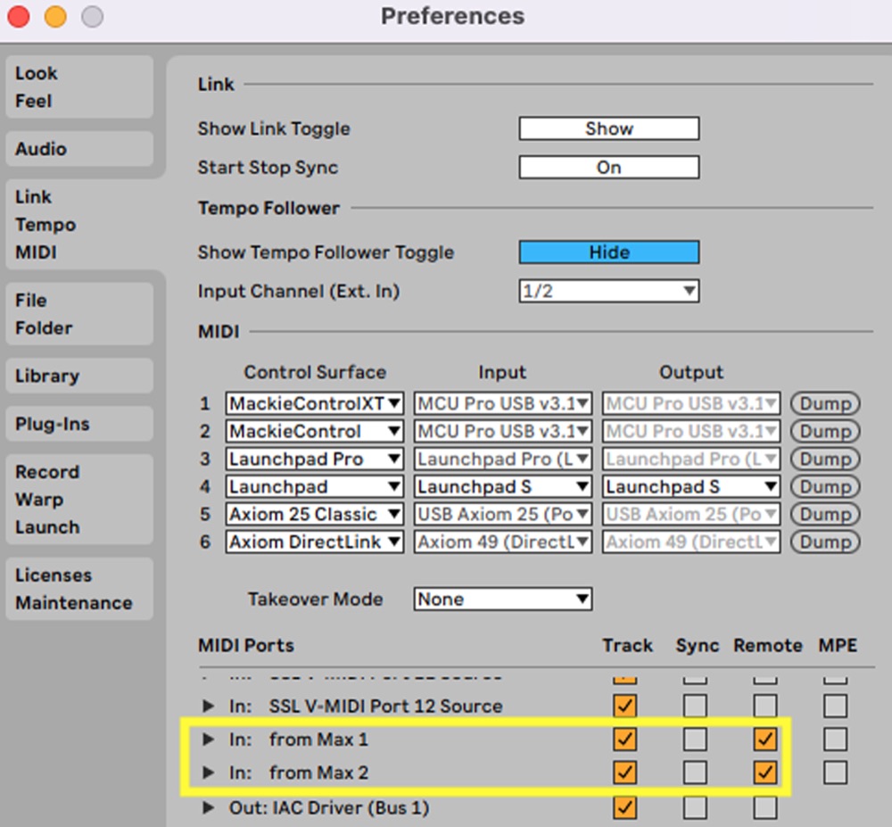
- Click on Preferences in the Live menu and ensure that remote is on for the MIDI port you are using, such as “from Max 1” (Figure 4.20).
- load an audio effect (e.g., EQ Eight) on a MIDI or audio track.
- send data from Max using the ctlout object.

- in Ableton, turn MIDI Map Mode on by pressing the “MIDI” button in the upper right part of the screen (Figure 4.21).
- select Device view (shift + tab to switch views) so that you can see the audio effect. Click the parameter you want to control (e.g., filter frequency), which will be highlighted in blue/purple (Figure 4.22).

- send MIDI CC messages to Ableton from Max (or from an external controller, an Arduino, etc.). You should see the MIDI CC # and parameter name in the Mapping Browser (upper left part of the window, see Figure 4.23).

- turn MIDI Map Mode off, and you should have control of the parameter from the external source.
Repeat this process to control multiple parameters simultaneously from one MIDI CC#. If you want to use one controller to manipulate different parameters in sequence (rather than simultaneously), set up duplicate tracks (or route the output of one track to the inputs of others), map the MIDI CC# to different parameters on the different tracks (e.g., reverb on track one, delay on track 2), and then mute/enable the tracks individually to create different sequential musical effects. Another possibility is to write the Arduino code so that it sends different MIDI CC#s depending on the input to the board (e.g., 128 produces MIDI CC# 14, and 129 produces MIDI CC# 15). During the piece, you could control the distance between your hand and the sensor and the parameter that the sensor is mapped to.
Before we get to these more exotic scenarios, we need to first address the primary issue of data filtering. In some scenarios, you may want to send the data to the computer, but do not want to use a program such as Max as an interlocutor. We learned how to transmit MIDI information directly from a microcontroller to a DAW in Project 12: MIDI Without Middleware, so if you are not using the Max environment for other purposes, the sensor data can be translated to MIDI and transmitted to the computer using the methods learned earlier.
There are also situations where you would want to filter and scale the data on the microcontroller rather than in external software. Say you want to use the sensor data to control a motor. There is no sense in piping the data to a computer, processing it, and then passing it back to the microcontroller when we could do all of that internally. Processing the data on the microcontroller reduces latency and bandwidth, and allows the possibility of a standalone device. To translate the sensor data on the microcontroller, the process used is similar to that featured in the Max example, except that we will use functions in place of max objects. The primary tasks are to filter outliers, remove redundancies, and smooth the data so that values don’t jump around too widely or too quickly.
There are several methods for smoothing data; here, we will consider two: a moving average (as in the max patch) and an exponential filter.
A moving average works by storing the values from a sensor input in a buffer (an array), which is then iterated through at each function call to produce a moving average: Declare an array for the buffer (dataReceived) of a particular size (bufferSize).
const byte bufferSize = 7;
int dataReceived[bufferSize];
Create a function called movingAverage. Store the current sensor value in the buffer at the position represented by the variable maIndex (which is declared as a static int) and increment maIndex. If maIndex is greater than the bufferSize, then reset the maIndex to 0 (this defines the size of the moving average). Iterate through the dataReceived buffer with a for loop, adding to the total each time. Divide the total (maTotal) by the size of the buffer (bufferSize) to produce the moving average.
void movingAverage() {
  static int maIndex = 0;
  dataReceived[maIndex] = currValue;
  maIndex++;
  if (maIndex >= bufferSize) {
    maIndex = 0;
  }
  int maTotal = 0;
  int movingAverage = 0;
  for (int i = 0; i < bufferSize; i++) {
    maTotal += dataReceived[i];
  }
  movingAverage = maTotal / bufferSize;
}
The buffer size affects the output data. Larger buffer sizes produce smoother results but are less sensitive to the most recently received values. Smaller buffer sizes will have the opposite influence.
Another approach is to weight values according to how recently they were received. For example, the most recent value receives a 3× weight (e.g., three of that value are included in the calculation instead of one), the second and third most recent values receive a 2× weight, and the other values receive a 1× weight. The “correct” size is the one that works for your application, so experiment! The moving average method achieves our goals of smoothing the data, but it can take up memory, which leads to another option.
Another technique for smoothing data is a recursive filter, described in “Three Methods to Filter Noisy Arduino Measurements” (2017). This filter is calculated using the following equation
where yn is the smoothed value, yn−1 is the previous smoothed value, xn is a new measurement, and w is a weight between 0 and 100. The higher the weight, the quicker the smoothed value responds to changes, but the smaller the amount of smoothing. The advantages of this method are that it requires little memory and that the amount of smoothing is controlled by a single parameter (the weight). You could do the calculation yourself, or you could use the ExponentialFilter example within the MegunoLink library, which we will do here. The code looks like this:
// Create a new exponential filter with a weight of 10
// and initial value of 0.
ExponentialFilter<long> ADCFilter(10, 0);

void recursiveFilter() {
  int rawValue = analogRead(0);
  ADCFilter.Filter(rawValue);
  int smoothedValue = ADCFilter.Current();
}
The smoothedValue can be used to generate notes, adjust tempo, or set a motor position. If you want to visualize the values without saving them and plotting them in Excel, the MegunoLink interface gives you a variety of useful options.
In all these cases, the amount of data generated is likely something you will have to address. If 10 values are received every millisecond with many repeated numbers, a moving average with a buffer size of five isn’t going to provide much smoothing. One approach to this problem is to sample the values from analogRead() at a slower rate (than occurs from loop). We don’t want to use a delay function, as that would block other processes, so we can instead use one of the timing methods described in Project 6. Set the timer to a specified interval, and when that interval has elapsed, read the sensor value. This is essentially what the speedlim object does in the Max patch in the previous section. The most appropriate interval for your situation depends on the nature of the input data. Reducing data in this way can give you a clearer picture of what you are working with and improve system performance.
The final task is to scale the data to the required range. This can be achieved with the map() function used in Project 10: Using MIDI Velocities to Control Dynamics. For example, if the sensor produced data in the range 50–800 and we wanted to scale this to the MIDI range of 0–127, we could use the following code:
data = analogRead(pin);
output = map(data, 50, 800, 0, 127);
Scaled data can be used to control a mechanical process, such as the ontime of a solenoid or the position of a dc motor. The latter is something we will be able to do once we accurately determine the motor’s position, which will be the focus of the next project.
- Which musical parameters can you map to the IR sensor? Which parameters are most musically useful? Why is this the case? What is it about the nature of the input that matches the sonic transformations?
- Try each of the filtering techniques. Collect the data and graph the results of each technique against each other. Which is most appropriate for your application and why?
- Explore ways that you can change the mapping of the sensor data to musical parameters in your DAW through the multiple-track and input message methods described earlier. What works best for a predetermined musical piece? What works best for an improvisation?
In Project 3, we learned how to control a DC motor, but an important aspect was absent: feedback. We made the DC motor turn, but we did not know where it started or where it stopped. Lacking feedback has ramifications: if we cannot move a motor to specific positions at specific times, we cannot produce pitches, rhythms, and dynamics with precision and accuracy. The remedy to this situation is to implement a device that provides feedback on the motor’s position, which we can then incorporate into an algorithm that determines how the motor moves.
- Read the position of a motor shaft using an encoder.
- Start a DC motor and then stop it after a specified position has been reached using data read from an encoder.
- Write a program that incorporates positional information from the encoder and a PID algorithm to move a DC motor to specified positions within specified time periods.
- Build a system that can tension a string using a guitar tuning machine. Connect the motor to the guitar tuning machine and use the algorithm from goal 3 to tune the string to each pitch in a major scale.
- Arduino Uno
- USB cable
- DC motor with encoder (e.g., Pololu 37D gearmotors)
- Motor driver (e.g., L293)
- Plank of wood (e.g., a 2 × 4)
- Standard guitar tuning machine
- Guitar string
- Coupler to connect the tuning machine to the motor shaft (e.g., 5mm-to-5mm flex coupler)
To determine the position of the motor shaft, we will use an encoder. An encoder senses the rotation of a disc connected to one end of the motor’s shaft. The disc has transparent and opaque sections that allow light from an LED to shine through, which are detected by a photosensor. The quadrature encoder we are using here has two sensing channels (A and B). The patterns of light and dark produce square waves of low and high voltage. The frequency of transitions between channels indicates the motor speed, while the order of the transitions indicates its direction (see Figure 4.24).

The first goal is to read data from the encoder. For this part, we will only need the following parts:
- Arduino connected to a computer
- Encoder
- Wires
The encoder has numerous wires (pictured in Figure 4.25)

that are connected to the following destinations:
| Color | Purpose | Possible Connection |
|---|---|---|
| Red | Motor power | Positive of motor controller |
| Black | Motor power | Negative of motor controller |
| Green | Encoder ground | Ground |
| Blue | Encoder power | 5V from microcontroller |
| Yellow | Encoder A output | To microcontroller pin |
| White | Encoder B output | To microcontroller pin |
The best performance will occur when the encoder is connected to interrupt pins on the microcontroller. This will vary by board, but for the Arduino Uno and Leonardo, pins 2 and 3 are interrupt pins, so we will use those. The circuit diagram is seen in Figure 4.26.

Install/include the Encoder Library from PJRC. In the Arduino IDE, navigate to Libraries in the left side panel, search for “Encoder,” and install the library (Figure 4.27):

Open up the Basic Example (File / Examples / Encoder / Basic):
#include <Encoder.h>
Encoder myEnc(2, 3);
// avoid using pins with LEDs attached

void setup() {
  Serial.begin(9600);
  Serial.println("Basic Encoder Test:");
}

long oldPosition = -1000;

void loop() {
  long newPosition = myEnc.read();
  if (newPosition != oldPosition) {
    oldPosition = newPosition;
    Serial.println(newPosition);
  }
}
Change the microcontroller pins that you connected to the encoder outputs in the line.
Encoder myEnc(2, 3);Start the serial monitor and by hand, turn the shaft of the motor. You should see the position of the shaft printing out on the serial monitor.
- Turn the motor shaft and notice how the position value changes. What is the smallest change that you can produce? What do negative values represent?
- Turn the motor shaft one full revolution and note the position value change. What do these experiments show you about the resolution of the encoder?
- Connect the encoder to non-interrupt pins (other than 2 and 3) on the Uno. Turn the shaft quickly: are the counts as accurate as when using the interrupt pins? What might explain this behavior?
Now that we can read the position of the motor shaft, let’s use that information to control the motor using an L293 H-bridge and a breadboard. Building on the circuit shown in Figure 4.26, connect two output analog pins from the microcontroller (e.g., 4 and 5) to the inputs of channels 1 and 2 on the L293. The outputs of channels 1 and 2 on the L293 connect to the motor power terminals of the motor/encoder. The circuit diagram is shown in Figure 4.28.
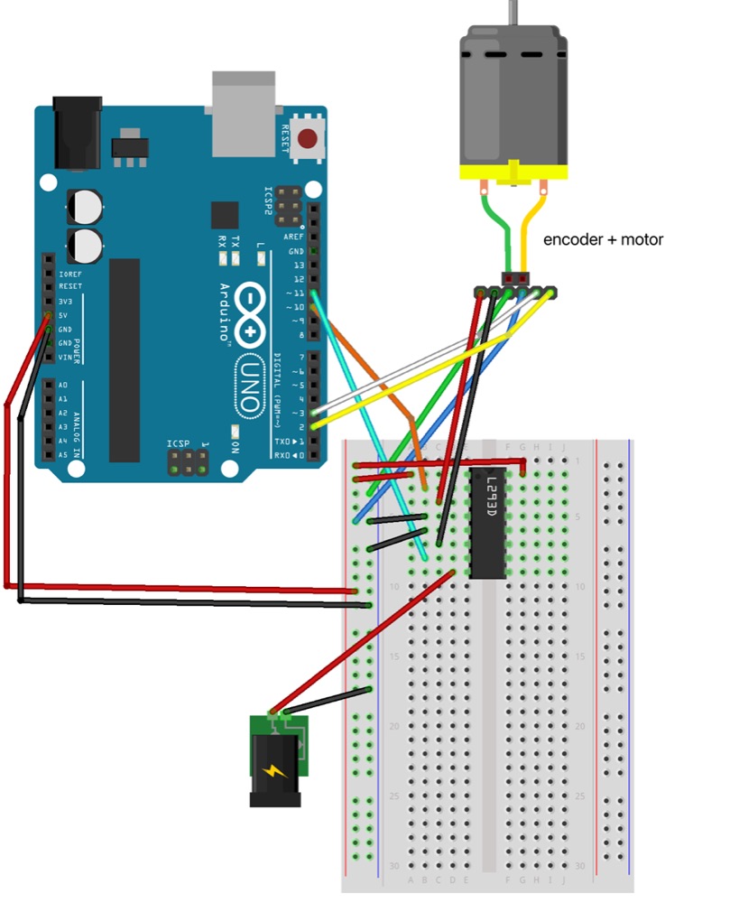
Include the encoder library and create the myEnc object from the Encoder class. Define the analog pins connected to the L293’s inputs. We will use pin 9 to control the clockwise direction, so create a variable called cw and assign it the value 9. Do the same with pin 10 and the counter-clockwise direction (call the variable ccw). We will also define a variable for pwm to control the motor’s speed.
#include <Encoder.h>
Encoder myEnc(2, 3);
int cw = 9;
int ccw = 10;
int pwm = 100;
Now to create functions. Thinking through the process, a user will input a position through the serial monitor, and the Arduino will read that data from the serial buffer. We can use the code from Project 8—Using the Serial Monitor with variables that are tailored to our current needs.
long goToPosition = 0;
const byte bufferSize = 8; // need constant for array bound
char dataReceived[bufferSize];

void setup() {
  Serial.begin(9600);
}

void readSerial() {
  static byte index = 0;
  if (Serial.available() > 0) {
    char inByte1 = Serial.read();
    if (inByte1 == '\n') {
      dataReceived[index] = '\0'; // terminate the string
      index = 0;
      goToPosition = atoi(dataReceived); // convert characters in buffer to integer
      Serial.println(goToPosition);
    }
    else {
      dataReceived[index] = inByte1; // assign value of inByte1 to array
      index++;
    }
  }
}
Read the encoder position with the code introduced earlier in this project:
long oldPosition = -1000;
long newPosition = 0;

void readEncoder() {
  newPosition = myEnc.read();
  if (newPosition != oldPosition) { // remove duplicate readings
    oldPosition = newPosition;
    Serial.println(newPosition);
  }
}
We also need functions to control the motor. In this case, we will write one function to make the motor move forward (clockwise) and another to turn the motor off.
void forward() {
  analogWrite(cw, pwm);
  analogWrite(ccw, 0);
}

void off() {
  analogWrite(cw, 0);
  analogWrite(ccw, 0);
}
Putting this all together, we will read data from the serial buffer and then read the encoder value. We then need to compare the goal position with the current position. If the current position is less than the goal position, run the motor forward. If it is equal to (or greater than) the goal position, stop the motor.
void loop() {
  readSerial();
  readEncoder();
  if (goToPosition - newPosition > 0) {
    forward();
  }
  else {
    off();
  }
}- Input a value into the serial monitor and run the motor. Look at the encoder values: Where do they stop relative to the goal position that was input? What explains this behavior?
- Modify the code so that when
off()is called, the encoder position is reset to 0 (you can write values to the encoder withmyEnc.write(value)). How can you write the code so that the motor doesn’t spin perpetually and instead waits for the next goal position to move to? - Add a function so that the motor can move backward. Write the code so that when a value is received, the program figures out if forward or backward movement is required, move to that position and then wait for the next goal position.
The previous experiments taught lessons about inertia and precision when using motors. Such behavior is amplified when more elaborate actuation mechanisms are used. Imagine a machine where a drumstick is attached to the shaft of a motor. The drum starts at a set position; the motor is activated; and when the drumstick reaches the desired location, as determined by an encoder, the motor is stopped. In an imaginary world where the components in the system were mass-less, this might work as expected. In our world, the inertia of the stick and the motor produce movement beyond the goal position, which, in the case of musical machines, can result in inaccurate pitches, timings, and dynamics. Addressing this issue requires an algorithm that determines the difference between the actual and desired setpoints and adjusts the motor’s position to reduce this error. A proportional-integral-derivative (PID) algorithm does just this.
PID is an example of a closed-loop system in which a goal is specified (set point), an action occurs to achieve that goal, the action is sensed and measured in some aspect such as position (process variable), and that information is “fed” back into the control system algorithm (compensator) to modify future instructions. There are several factors that determine the response of a PID system. The rise time is the time required to go from 10% to 90% of the steady-state or final value. The percent overshoot is the amount the system exceeds the final value (e.g., due to inertia), expressed as a percentage of the final value. The settling time is the time required for the process variable to remain within a smaller range (e.g., 5%) of the final value. The steady-state error is the difference between the set point and the process variable. Figure 4.29 shows the performance of a system using PID control (blue) in comparison with one that simply turns the motor off when the goal position is reached (green). The goal position (750) is represented in orange. The lesson here is that motors are not theoretical constructs that can stop on a dime: it takes time for a motor to come to rest after power is disconnected. The results in Figure 4.29 were produced by the system described in this project.

The Proportional-Integral-Derivative (PID) control algorithm has three individual parameters for which it is named. The proportional controller depends on the difference between the set point and the process variable (current error). Its output is the error e(t) multiplied by a gain constant Kp. Increasing proportional gain will reduce rise times but can increase oscillations in the process variable and produce steady-state error. The integral controller reduces errors by compensating for them over time. It does this by accumulating the error over a temporal interval dt and multiplying it by a constant Ki until the error converges to zero (i.e., the set point has been reached). Overshoots and oscillations can persist after tuning Kp and Ki, necessitating another controller. The derivative controller attempts to minimize sudden changes in error by multiplying the rate of change of the error by a constant (Kd). Summing these three controllers yields the PID algorithm’s output. We can represent these relationships mathematically in the following equation
where
| u(t) | PID control variable | e(t) | error value |
| Kp | proportional gain | Ki | integral gain |
| Kd | derivative gain | de | change in error value |
| dt | change in time |
Tuning these values is necessary to reduce the error expeditiously while minimizing overshoots, oscillations, and instability. This is accomplished by changing the K constants. One way of doing this, called the trial and error method, is by setting the Ki and Kd terms to 0 and increasing Kp until the output of the loop oscillates. Figure 4.30 shows the performance of a PID algorithm controlling a DC motor with an encoder when experimenting with a variety of values for Kp (Ki and Kd were set to 0) when inputting a set point of 1000.

Lower values for Kp resulted in large steady-state errors. As the constant increased, the rise time shortened, but this was also accompanied by values that exceeded the set point and took longer to settle. Finding the right value becomes easier when the character of each one is articulated and understood. Visualizing the information is often helpful.
Once Kp has been set to obtain a response that meets speed requirements, Ki is increased to stop the oscillations and adjusted to minimize steady-state error. Kd is then increased until the system reaches the set point within an acceptable time. Often, these terms need to be tweaked relative to one another to find the right balance. It is also possible not to use one of the controllers (e.g., a PI controller).
The following code (adapted from Das, 2021) uses an encoder in conjunction with a PID algorithm to set a motor at specified positions. First, include the PIDController library, define the pins for the encoder and motor, and set the PID parameters.
#include <PIDController.h>
#define ENCODER_A 2
#define ENCODER_B 3
#define MOTOR_CW 10
#define MOTOR_CCW 11
#define __Kp 260  // Proportional constant
#define __Ki 2.7  // Integral Constant
#define __Kd 2000 // Derivative Constant
Create an object pidcontroller from the PIDController class:
PIDController pidcontroller;In setup(), start serial communication (to read encoder and PWM values) and initialize pins to inputs and outputs as necessary. Here we are also going to initialize the pidcontroller instance, establish the PID arguments, and bound the PID output:
pidcontroller.begin();
pidcontroller.tune(__Kp, __Ki, __Kd); // PID arguments kP, kI, kD
pidcontroller.limit(-255, 255); // Limit the PID output
The final command in setup is to attach an interrupt to ENCODER_A using the Arduino function attachInterrupt, which will call the function encoder() on the RISING edge of the generated pulse.
attachInterrupt()
Syntax: attachInterrupt(digitalPinToInterrupt(pin), ISR, mode)
attachInterrupt(digitalPinToInterrupt(ENCODER_A), encoder, RISING);Interrupts can provide periodic, timed operations that do not bog down the main program, which is what is needed when polling a rotary encoder. Which pin is used depends on the board: on the Arduino Uno (and other 328-based boards) pins 2 and 3 can be used for interrupts, while pins 0, 1, 2, 3, 7 can be used on the Micro or Leonardo. The Interrupt Service Routine (ISR) should be as short and fast as possible. It cannot have any parameters, and it cannot return any values. Some functions, including delay(), millis() and micros() will not work in an ISR as they use interrupts themselves. Variables shared between an ISR and the main program should be of type volatile. The mode indicates the pin state that will run the interrupt, which can be LOW, CHANGE (when the pin changes value), RISING (low to high), FALLING (high to low), and HIGH (on the Due and Zero).
This function specifies that when the signal on ENCODER_A (pin 2) goes from low to high, it will run the following ISR called encoder(). The latter will increment the encoder count if ENCODER_B (pin 3) is HIGH and decrement the count if it is LOW.
void encoder() {
  if (digitalRead(ENCODER_B) == HIGH)
    encoder_count++;
  else
    encoder_count--;
}
The variable encoder_count needs to be declared at the beginning of the program as a volatile long:
volatile long int encoder_count = 0; // stores the current encoder countMake a function called readSerial() (as we did in previous examples in this chapter) that puts characters received from the serial monitor into a buffer that is converted into an integer variable called integerValue. This variable also needs to be declared at the beginning of the program.
As in the previous example, we also need functions that will control the motor. One will control the motor in the clockwise direction (motor_cw), and one will control the motor in the counter-clockwise direction (motor_ccw). Each of these functions will return nothing, and one parameter (power, type int) will be passed to them. In each function, write the appropriate pin (e.g., MOTOR_CW when moving clockwise) HIGH and the other pin (e.g., MOTOR_CCW) LOW. Use the power variable to set the PWM value in each analogWrite() function. If power is not above a threshold that you define, write both pins LOW.
With constituent functions defined, in loop(), we will read data in the serial buffer by calling readSerial(), and then use the input value (integerValue) to specify the goal position using the method setpoint:
pidcontroller.setpoint(integerValue);Use encoder_count (established in the ISR) in the PID compute method to derive the appropriate PWM value, which is stored in the variable motor_pwm_value (which also needs to be declared at the beginning of the program as type int).
motor_pwm_value = pidcontroller.compute(encoder_count);Test the value: if it is greater than 0, turn the motor counter-clockwise by calling the motor_ccw function (passing it the motor_pwm_value), else move it clockwise.
if (motor_pwm_value > 0)
  motor_ccw(motor_pwm_value);
else
  motor_cw(abs(motor_pwm_value));
We want to see encoder_count and motor_pwm_value to assess how the system is performing. Try printing these values to the serial monitor. What happens? This leads us to another important lesson:
Lesson: When data is abundantly produced (such as readings from an encoder), it can cause delays in the values printed and can affect the performance of the system. In these cases, reduce redundant values, output data at a less frequent rate (e.g., by using a timer) or both.
Here, you will likely want to remove redundancies using the method introduced earlier in this project for the Encoder library.
Another piece of information we are interested in is how long it takes from the moment the message is received to the moment the motor stops. We can use millis() to make a timer as we did in Project 6. Think about where the timer should start, where it should stop, and when the values should be printed.
We can now experiment with the different parameters of the PID:
- Use the trial-and-error method described earlier. Examine the output data to see how the PID parameters affect positional accuracy and the time required to reach that position. Tweak the values until you get a balance that works for your application.
- Change the threshold of the power value that moves the motor in the
motor_cwandmotor_ccwfunctions (e.g., if power is >100 then move the motor, otherwise write both motor pins low). How does this value affect the system’s performance?
You can now make a DC motor move to a specific position in a given period of time. This approach is powerful and can be used in a variety of musical contexts, from controlling the dynamic range produced by a machinic percussion player to changing the pitch of a string instrument.
In this chapter, we learned how to make different devices talk to each other to control electromechanical systems. The first set of projects involved communication, including sending and receiving data using the serial monitor (Project 8), playing a percussion system using a DAW such as Ableton Live (Project 9), using MIDI velocities to control musical dynamics (Project 10), maintaining data integrity as information is transmitted between systems (Project 11), communicating MIDI without intermediary software programs (Project 12), using ethernet and Open Sound Control (OSC) to send information (Project 13), and controlling actuators with external hardware devices such as Eurorack modules (Project 14). The second set of projects involves incorporating feedback by receiving and processing data from analog sensors (Project 15) and controlling motors with PID (Project 16). Feedback provides information to a machine about its internal state and its external environment, which facilitates improved performance and interaction with others. One method or configuration is not necessarily the best: the one that will work for you depends on your project’s requirements. By experimenting with different technologies and methods, you will become more proficient in defining the approach that suits your needs. You will also be inspired to combine, extend, and apply the basic ideas here to different contexts to produce a diverse set of machines that can interact with humans and each other to make music!
- Cristian, V. (2017). Strain gauge [Graphic]. Own work. commons.wikimedia.org
- Das, D. (2021, February 3). Design an Arduino based encoder motor using PID controller. Circuit Digest. circuitdigest.com
- Eitel, E. (2014, May 7). Basics of rotary encoders: Overview and new technologies. Machine Design. machinedesign.com
- Margolis, M. (2010, August 21). Sending and receiving string via UDP. Arduino. arduino.cc
- oomlout. (2009). Sharp GP2Y0A21YK infrared proximity sensor [Graphic]. Sharp Distance Sensor–IC-PROX-01. commons.wikimedia.org
- OpenSoundControl. (2021, June 5). opensoundcontrol.org
- Three methods to filter noisy Arduino measurements. (2017, May 20). MegunoLink. megunolink.com