Matter is composed of atoms, which contain a nucleus orbited by negatively charged electrons. In some materials, such as wood and glass, electrons remain with their atoms. Consequently, these materials do not conduct electricity particularly well, making them good electrical insulators. In other materials (such as metals), electrons move freely, transferring energy from one location to another. These materials are good conductors of electricity and are the basis for the complex world of electronics.
What makes these electrons move, and how can we control the process? Coulomb’s Law tells us that like charges repel and opposite charges attract with a force that depends on the charge and the distance between them:
where k is a constant depending on the medium, Q1 is the charge of object 1, Q2 is the charge of object 2, and d is the distance between the two objects. Electrical current flows from a region of high charge (high potential) to a region of low charge (low potential). Current can flow in either direction through a conductor. Alternating current (AC) periodically changes direction and magnitude (this is what is output from the outlets in your house) while direct current (DC) flows in only one direction (this is the kind we will primarily be working with in this chapter). Sources of electrical power have a positive terminal (+) and a negative terminal (−), which electricity flows between. Connecting the terminals with a conductor, such as a wire, facilitates the flow of electricity, thus completing the circuit (Figure 3.1.1). Inserting a load (such as a lightbulb or motor) into a circuit enables it to consume power and convert it into another form of energy.

Lesson: Electrical flow requires a positive terminal connected to a negative terminal. There must be a load in a circuit, or else the electrons will flow very quickly between the terminals, creating heat and a potentially dangerous situation.
The direction of electron flow in a circuit can be confusing. Benjamin Franklin conducted early experiments on this phenomenon and concluded that charges move from positive to negative (known as conventional current flow). In real metallic conductors, charges move in the opposite direction, from negative to positive (known as electron flow). Because conventional current flow was followed for so long and the direction doesn’t affect many mathematical calculations, it is still used today in representations of electric circuits.
The flow of electricity is analogous to the flow of water through a pipe. The flow rate, or the number of electrons that pass a point in a conductor in a given amount of time, is known as current or amperage, and it is measured in amps (one amp is 6.24 × 10¹⁸ electrons passing a point in 1 second). The potential for energy to move, or the “pressure” that pushes the electrons in a conductor, is the voltage, which is measured in volts. In the language of physics, voltage is a measure of electric potential energy to move a charge from one point to another. That which impedes the flow of electrons is known as resistance and is analogous to the water pipe size (the resistance of a wire depends on its length, thickness, and temperature). The relationship between voltage (V), current (I), and resistance (R) is seen in Ohm’s Law:
Current and resistance are inversely proportional, which agrees with intuition: increase the resistance and less electricity will flow. Rearranging the formula to
shows us that given a particular resistance, increases in voltage will result in increases in current, and vice versa. If the voltage is increased and current remains the same, the resistance in the circuit must increase. Power (P), measured in watts, is the product of voltage (V) and current (I):
Electricity and magnetism have a special (and amazing) relationship. When a magnet is moved close to a metal wire, it forces the electrons within that wire to move. This is the fundamental principle (albeit a simplified one) behind electric generators. A motor works on the same principles, but in the other direction. A motor is an electromagnet, which is essentially a wire wrapped around a metal bar (such as iron). When electricity flows through the wire, a magnetic field is generated in the metal bar, which subsequently becomes a magnet with north and south poles. Many actuators, which move or control mechanisms or systems, work according to the same principle. The projects that follow later in the chapter will incorporate actuators, including solenoids, DC motors, stepper motors, servo motors, and pneumatic actuators.
Harnessing the potential of electricity is accomplished via electrical components that perform specific functions. Resistors, capacitors, and transistors are core parts of electronic circuits that are often used in combination.
Resistors limit current. They come in a variety of values, measured in ohms (Ω), kilo-ohms (kΩ, ×1,000), or megohms (MΩ, ×1,000,000). These values are indicated by the colored stripes on the resistor as seen in Figure 3.1.2.

In practice, it is usually acceptable to use a resistor value within 15% of what is specified in the schematic. With that said, be careful to use the indicated power rating (watts). If a power rating is not detailed, then ¼ or ½ watt resistors should usually be sufficient.
When resistors are connected in series, the total resistance (RT) is the sum of the resistors (R1, R2). When resistors are connected in parallel, the total resistance is the product of the resistors divided by their sum (Figure 3.1.3):

For three or more resistors in parallel, the equation is
As current flows through a circuit’s resistance, some voltage is lost, known as the voltage drop. Voltage drop can be mitigated by shortening cable runs and/or increasing conductor size (i.e., wire). The concept of voltage drop is central to a voltage divider, which converts a higher voltage into a lower one using two resistors. The circuit can be seen in Figure 3.1.4. Voltage out (Vout) is determined by voltage in (Vin) and the ratio of the two resistors (R1 and R2):
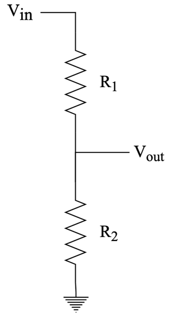
Example: If the input voltage was 14 V and R1 and R2 were both 100 Ω, then the output voltage would be 7 V.
Voltage dividers are useful when a component requires a variable input voltage. A potentiometer contains a wiper that moves along a resistive strip to form an adjustable voltage divider, which is used in applications such as volume control. Potentiometers can be rotary (e.g., trimpots) or linear (e.g., sliders). Force-sensitive resistors (FSR) modify the resistance in a circuit depending on how much force is applied to the resistive element. The voltage across a component can be measured with a voltmeter or a multimeter, which indicates how much voltage has been consumed. It is important that each component receives the voltage that it is rated for.
Capacitors store electrical charge. A simple capacitor consists of two conductive plates separated by an insulating material (e.g., ceramic). Capacitance, the ability to store electric charge, is specified in farads (F), microfarads (1µF = 10−6 F), and picofarads (1 pF = 10−12 F). Capacitors come in a variety of shapes and sizes (Figure 3.1.5). Some capacitors are not polarized (such as the small orange ceramic ones), which means it doesn’t matter which way they are attached to a circuit. Other capacitors (e.g., electrolytic) are polarized, meaning they have a positive and negative leg that must be connected to the circuit as indicated. The negative leg of an electrolytic capacitor is usually marked by a “−” sign or a colored strip, and the positive leg is usually longer than the negative leg.

Capacitors charge quickly, though this rate can be slowed by resistors. A capacitor can be discharged quickly by connecting the two plates (legs) together, or the rate can be slowed by an intermediary resistor (R1). Capacitors and resistors in the same circuit form a resistor-capacitor (RC) circuit (Figure 3.1.6), which can filter a signal by attenuating some frequencies and not others.

Capacitors serve multiple roles: storing and discharging energy, smoothing voltage, filtering signals, and setting timing or oscillation frequencies.
Lesson: Capacitors can store a charge long after power to the circuit has been disconnected. Never touch them when they contain charge!
An inductor stores energy in a magnetic field when an electric current flows through it and can release that energy almost instantly when needed. Unlike capacitors, which oppose changes in voltage, inductors oppose changes in the current. A basic inductor circuit is formed by a power source (e.g., a battery), a resistive element (e.g., a lightbulb), and a coil of wire around a core (such as an iron rod) connected in parallel with the resistive load (Figure 3.1.7). When voltage is applied to the circuit, the current flows through the coil, generating a magnetic field, that induces back electromotive force (back EMF) that opposes the current. Little current flows through the inductor as a result and instead flows through the light bulb because it presents the path of least resistance. As the magnetic field builds, the current flows more freely through the inductor and back EMF dissipates. When the magnetic field has reached its maximum, the inductor presents little resistance so the current flows through it and not the lightbulb (which presents relatively greater resistance). When the circuit is switched off, the induced voltage works in the opposite direction, pushing the current through the light bulb until the energy stored in the magnetic field dissipates. In summary, when the current increases, inductors resist the change with an opposing force. When the current decreases, inductors resist the change by pushing electrons through the circuit. Inductors help stabilize changes in the current. Inductors are used to store and transfer energy in power supplies, filter high-frequency noise, and for devices such as transformers and motors.

The capacity of an inductor depends on the number of coils (more coils = more inductance), the material of the object that the coil is wrapped around, the cross-sectional area of the coil (more area = more inductance), and the length of the coil (shorter coil = more inductance given the same number of coils). Because of their current-maintaining disposition, inductors are often used in power supplies.
Transistors allow a small amount of the current attached to one lead to control a large amount of the current attached to another. This basic function makes them useful for switching or amplifying electronic signals. There are two main types of transistors: bipolar and field-effect. Bipolar junction transistors (BJTs), which are current-controlled, involve three layers of silicon (a primary semiconducting material) in the order NPN or PNP (the “N” refers to silicon with phosphorus atoms, while the “P” refers to silicon with boron atoms, both of which affect how the material behaves). In both examples, the middle layer called the base (B) controls how the current flows through the other legs of the component, called the emitter (E) and the collector (C). The type of transistor determines whether the current flows from emitter to collector (PNP) or from collector to emitter (NPN), which in turn determines how the transistor is connected to other components in the circuit (see Figure 3.1.8).

A field-effect transistor (FET) functions in a similar way, except that the three leads are called the gate, drain, and source. FETs are useful because they can be controlled by a very small input voltage. We will look more at a particular kind of FET, the MOSFET, in Project 1: Solenoid Percussion.
Wire provides a path for electrical charge to travel between components. Metals such as copper are good conductors of electricity, and thus are commonly used to make wire. Wires are typically sheathed in an insulating material such as rubber or plastic, and multiple wires bound together constitute a cable. Wire is solid core (one piece of copper) or stranded (many thin strands of copper that are bunched together). When making breadboard connections, solid-core wire is often easier to work with. Stranded wire can be more flexible, which is more advantageous when making connections between different parts of a system (particularly over longer distances). The current the wire can safely carry depends on the wire thickness, or gauge, the ambient temperature, and the number of individually insulated conductors. The thicker the wire, the lower the ambient temperature, and the more individual conductors, the more current the wire can handle. Table 3.1.1 shows the relationship between wire gauge, resistance, and amperage capacity. This is only a guide: always check the wire manufacturer’s documentation for details about the wire you are using.
| AWG gauge | Conductor diameter (in.) | Ohms per 1000 ft. | Max amps, chassis wiring | Max amps, power transmission |
|---|---|---|---|---|
| 4/0 | 0.46 | 0.049 | 380 | 302 |
| 3/0 | 0.4096 | 0.0618 | 328 | 239 |
| 2/0 | 0.3648 | 0.0779 | 283 | 190 |
| 1/0 | 0.3249 | 0.0983 | 245 | 150 |
| 1 | 0.2893 | 0.1239 | 211 | 119 |
| 2 | 0.2576 | 0.1563 | 181 | 94 |
| 3 | 0.2294 | 0.197 | 158 | 75 |
| 4 | 0.2043 | 0.2485 | 135 | 60 |
| 5 | 0.1819 | 0.3133 | 118 | 47 |
| 6 | 0.162 | 0.3951 | 101 | 37 |
| 7 | 0.1443 | 0.4982 | 89 | 30 |
| 8 | 0.1285 | 0.6282 | 73 | 24 |
| 9 | 0.1144 | 0.7921 | 64 | 19 |
| 10 | 0.1019 | 0.9989 | 55 | 15 |
| 11 | 0.0907 | 1.26 | 47 | 12 |
| 12 | 0.0808 | 1.588 | 41 | 9.3 |
| 13 | 0.072 | 2.003 | 35 | 7.4 |
| 14 | 0.0641 | 2.525 | 32 | 5.9 |
| 15 | 0.0571 | 3.184 | 28 | 4.7 |
| 16 | 0.0508 | 4.016 | 22 | 3.7 |
| 17 | 0.0453 | 5.064 | 19 | 2.9 |
| 18 | 0.0403 | 6.385 | 16 | 2.3 |
| 19 | 0.0359 | 8.051 | 14 | 1.8 |
| 20 | 0.032 | 10.15 | 11 | 1.5 |
| 21 | 0.0285 | 12.8 | 9 | 1.2 |
| 22 | 0.0253 | 16.14 | 7 | 0.92 |
| 23 | 0.0226 | 20.36 | 4.7 | 0.729 |
| 24 | 0.0201 | 25.67 | 3.5 | 0.577 |
| 25 | 0.0179 | 32.37 | 2.7 | 0.457 |
| 26 | 0.0159 | 40.81 | 2.2 | 0.361 |
| 27 | 0.0142 | 51.47 | 1.7 | 0.288 |
| 28 | 0.0126 | 64.9 | 1.4 | 0.226 |
| 29 | 0.0113 | 81.83 | 1.2 | 0.182 |
| 30 | 0.01 | 103.2 | 0.86 | 0.142 |
| 31 | 0.0089 | 130.1 | 0.7 | 0.113 |
| 32 | 0.008 | 164.1 | 0.53 | 0.091 |
Other components you may encounter include switches (which interrupt current), relays (electromagnetic switches), transformers (which can isolate parts of a circuit, convert power, and match impedance between devices), diodes (which permit current to flow only one way), and optical components. We will look at some of these in more detail in the Projects section and in the next chapter.
Motors are ubiquitous in musical machines, and you will work with a variety of them (DC, stepper, servo) in the projects in this chapter. While detailed descriptions of each motor type are covered in the projects, there are several general considerations to keep in mind when selecting a motor. Torque, speed, and space requirements provide a basis for motor selection. Some of these may be more constrained than others, depending on the application. For example, if you are trying to couple a DC motor to a guitar tuning machine, you have a limited amount of space to work with. Find a motor that fits your size requirements and then change the gear ratios to deliver the torque and speed that you need. There will be compromises — for example, increasing the torque exerted by the motor will lower rotational speeds. Determining these requirements first will save time and money. I have often seen groups obtain a motor for their project, spend significant time and effort designing and building the machine, and then later realize that they chose the wrong motor. The best case in such situations is that an alternative motor can be plugged into the design, primarily resulting in costs of time and money. Motors can be expensive (they can cost hundreds of dollars) and can take months to manufacture (if ordering a custom motor), so these costs can be significant. A less desirable case is that the design needs to be significantly modified, which also results in additional costs.
Lesson: Determine torque, speed, and space requirements when choosing a motor. It will save you time and money.
A basic circuit consists of a power source (such as a battery or power supply) and a load connected between its terminals. As electrons flow from one terminal of the power source through the load to the other terminal, work is done (e.g., moving a motor or lighting a lamp). A series circuit (Figure 3.1.9) is formed when an electrical current flows through objects in sequence. In a series circuit, the current at any point is the same.

A parallel circuit (Figure 3.1.10) is formed when electrical current branches and flows through load A and load B independently.

More advanced circuits may contain components that are connected both in series and in parallel.
When conductors (such as wires) are placed across the connections of a component, a “shortcut” is formed along which electrical current can flow, which can cause dangerous situations (this is therefore known as a short circuit).
Lesson: Do not place a conductor across the connections of a component: this can create dangerous situations.
Circuit (signal, reference) ground refers to the part of the circuit that is at zero voltage, which serves as a reference point for other voltage measurements (we learned that voltage is a measurement of electric potential between two points: ground is one of the latter). In circuit diagrams, ground is represented with the symbols in Figure 3.1.11:

Earth ground (a related but separate concept) refers to the way in which alternating current lines (such as the ones in your house) are connected to a metal rod that is connected to the earth. The earth is a good conductor, so it makes a good return path for electrons. Metal enclosures (such as the case of a computer) are connected to this ground line (via the bottom prong in US outlets). The reason for this is that if a wire disconnects and touches the metal enclosure, and then you touch the metal enclosure, electricity flows through the connection to ground rather than through you!
All parts of a circuit should be connected to a common ground, which provides a stable voltage reference so that components and subsystems can interface properly. This is particularly important when multiple power supplies are involved.
Lesson: Connect the parts of your circuit to a common ground or else the circuit may not work properly.
In some electronic devices, ‘ground’ is not connected to earth but a large conductor (e.g., metal chassis, ground plane on a circuit board), providing a common return path for current from different parts of the circuit.
The primary criteria for choosing a power source are the voltage components are rated for and the current they will draw. The kinds of circuits that are the focus of this book typically require one voltage level for logic (5 V or 3.3 V, depending on the microcontroller) and (at least) another for the actuators (e.g., 12 V). The required current capacity of the power supply can be determined by summing the current drawn by each component in the system, considering steady-state current (normal operation after transient effects) and peak current (transients from startup and motor or solenoid activation). Check datasheets and do tests to confirm these levels (using either a multimeter or a benchtop power supply with a current reading). When choosing a power supply, leave headroom for the steady-state current draw (10–20%) and up to 50% for systems that contain components that will produce transient current spikes (e.g., solenoids) — it is better to have more than less. Drawing more current than a power supply can deliver can lead to performance issues and component damage.
Batteries make mobile and wireless applications possible. Battery capacity is listed in ampere-hours (Ah) or milliampere-hours (mAh), which is how much current the battery can deliver over a period of 1 hour. A single battery may suit the needs of the project. If more voltage or current is required, then batteries can be connected in series (Figure 3.1.12). The total voltage of the circuit equals the sum of the batteries’ voltages; the current remains the same. For example, two 5 V, 1,000 mAh batteries connected in series would produce a 10 V, 1,000 mAh power supply.

When batteries are connected in parallel (Figure 3.1.13), the capacity of each battery is added together while the voltage remains the same. For example, two 1.5 V, 1,500 mAh batteries connected in parallel can deliver 1.5 V with a capacity of 3,000 mAh.

An alternative to batteries is a power supply that converts AC power from a wall outlet into the DC power required by a circuit. A linear power supply takes an AC input, steps the voltage down with a transformer, then rectifies (allows electricity to flow in only one direction) and filters the input to produce a DC output. A switching power supply takes an AC input, filters and rectifies it to DC, converts it back to AC at a high switching frequency, steps the voltage down with a transformer, and then rectifies and filters it to DC. Linear supplies produce low noise because there is no high-frequency switching but are less efficient and use bigger components (transformer and filter). Switching power supplies are more efficient and use smaller components.
Check the polarity symbol that is printed on the case of the power supply, which indicates the configuration of the barrel plug:
- Center positive: center (tip) is positive while barrel (ring) is negative (Figure 3.1.14).

- Center negative: center (tip) is negative while barrel (ring) is positive (Figure 3.1.15).

Connect the power supply to a circuit using a 2.1 mm barrel jack. Each of the pins of the barrel jack plug into its own row on a breadboard. The pins of the barrel jack are numbered on the datasheet, which correspond to the connections on the barrel connector on the power supply (Figure 3.1.16):

| Pin | Description |
|---|---|
| 1 | The center (tip) pin, which typically connects to V+ (furthest from jack). |
| 2 | Connects to the barrel (ring), typically connects to gnd (closest to jack). |
| 3 | Used to detect if a plug is inserted (between 1 and 2). When no plug is inserted, pin 3 is shorted to pin 2. You may leave pin 3 unconnected. |
When connecting a power supply to an AC outlet, the live wire delivers power to the device, the neutral wire provides a return path for the current provided by the live wire, and the ground wire provides a safety path to earth as described earlier. The following are North American conventions:
| Line type | Abbreviations | Colors |
|---|---|---|
| Live | L / hot | Black (primary) or red (secondary) |
| Neutral | N | White or gray |
| Ground | E | Bare or green |
These connections correspond to 120 VAC (Volts Alternating Current) outlets (North America) as shown in Figure 3.1.17:

Circuits often require different voltages. One possibility is to use a power supply with multiple rails supplying different voltages (e.g., an ATX power supply). Another possibility is to use separate power supplies, such as one for logic (e.g., 5 V) and one for motors (e.g., 12 V). Separate power supplies are a good idea when simultaneously working with audio and actuators, as noise from the actuator circuits can become audible when amplified.
Lesson: Never plug a power supply (e.g., 12 V) into the same rail or row that another power supply (e.g., 5 V from the Arduino) is connected to: you could damage components, the Arduino, and your computer!
Another possibility is to use a voltage regulator or converter to transform an input power source into one that satisfies the requirements of the circuit’s components. For example, the LM7805 takes an input of 7 V–35 V and outputs 5 V at up to 1.5 A, which can be used to power the logic-level devices in a circuit (such as a microcontroller).
Schematics are maps of electrical circuits. They enable designs to be notated in a standardized way and communicated to others. For the builder, they provide a blueprint to follow to realize a circuit design. Schematics can be intimidating for the uninitiated with their panoply of interconnected lines and unfamiliar symbols. Fear not though, for understanding schematics involves two basic processes: (1) identifying the component symbols and (2) understanding how such components are connected together.
Components that you are likely to encounter in schematics include the following (Figure 3.1.18): resistors, potentiometers (variable resistors), capacitors (polarized and non-polarized), diodes, motors, inductors, switches, batteries, positive and negative supply voltage, ground, transistors (BJT and MOSFET), amplifiers, LEDs, photodiodes, photoresistors, and optocouplers.

Components are often labeled with an abbreviation for their name:
| Abbreviation | Component |
|---|---|
| R | Resistors |
| C | Capacitors |
| L | Inductors |
| S | Switches |
| D | Diodes |
| Q | Transistors |
| U or IC | Integrated circuits |
| Y or XTAL | Crystals and oscillators |
and a numerical identifier for that component (1, 2, 3…). For example, R1 and R2 represent two resistors in a circuit.
Lines between components mean they are connected. In Figure 3.1.19, the positive terminal of the battery is connected to the anode of the LED, and the cathode is connected to a resistor connected to the battery’s negative terminal.

When lines cross, they are usually not connected, but this notation is ambiguous. When a line jumps over another line, they are not connected. When they cross with a dot, they are connected. These configurations are seen in Figure 3.1.20.

Power usually flows laterally or from top to bottom in a schematic. When making a schematic, it is good practice to keep lines as short as possible and use 90° angles. More complex schematics are often broken into blocks according to function (e.g., power input, microcontroller, etc.) to make them more legible. We will look at examples of schematics in the Projects section.
With the ability to decode a schematic, the next step is to build it. Perhaps the easiest method is the breadboard, which allows components to be connected quickly and reversibly (which is important because we all make mistakes when building circuits) without soldering connections. A breadboard is pictured in Figure 3.1.21:

A wire, component lead, or IC pin inserts into a hole of the breadboard, which is connected to a metal clip. The metal clip is attached to a metal strip at the bottom of the breadboard that is connected to other clips/holes, thus enabling connections to be made. The internal metal strips connect columns a–e and f–j in each numbered row. For example, a wire in row 1, column a, would be connected to a component lead in row 1, column b, but not to a wire in row 2, column a or row 1, column i. There are also rails for power and ground on the right and left of the board, where the entire positive column is connected by internal metal strips, as is the negative (the two are not connected to each other!). Note the power rail on the left of the breadboard is not connected to the power rail on the right of the breadboard (the same is true for the negative rail), so the pairs must be joined by wires if they are to be used (remember that the circuit requires a common ground). ICs are typically positioned so that their left pins go in the left side of the board (column e) and the right side of their pins go in the right side of the board (column f), ensuring none of the pins are connected to each other. There is a semicircular notch on one end of the IC that should be directed toward the top. This is important, as each pin of the IC has a specific function — you do not want to orient the IC upside down!
When electrical devices and microcontrollers are connected in a circuit, we can control some of those devices (such as actuators) via computer programs. Microcontrollers are integrated circuits that contain processor cores, memory, and input/output capabilities. They contain instructions written in code that allow electrical signals to be sent and received between system components. Platforms such as Arduino have made programming microcontrollers and integrating components accessible to a wide range of people. Given the platform’s accessibility and ubiquity, we will use an Arduino Uno in the project examples. Other microcontrollers (e.g., Teensy, Raspberry Pi) can be used in the examples just as easily, though the code examples here will need to be adapted.
With an Arduino Uno in hand, visit arduino.cc to use either the web editor or desktop IDE to program the board. Open the Blink sketch (File / Examples / Basics). Make sure that you have the proper board and port selected (Tools / Board; Tools / Port on the desktop IDE). Verify the sketch and upload it to your board.
There are two primary parts of an Arduino program: setup() and loop(). The setup function initializes variables, pin modes, and so on, and runs once after the board resets. For example, pins can be configured to function as inputs or outputs. The loop function executes commands perpetually (unless power is disconnected or it is told to stop). Neither function returns a value, so both are preceded by the term void. Commands within a function are enclosed in brackets.
/*
comments go between these symbols
*/
//this is another way to indicate comments

void setup() {
  //initialize values, set pinmodes, etc.
}

void loop() {
  //this is where the program goes
}
Lesson: Look at the Blink sketch and identify the commands used in the setup and loop sections of the program. Pay attention to the syntax of the commands and figure out what each part does. If you have questions about a particular aspect of a command, consult the Arduino Language Reference pages (arduino.cc/reference/en). Become familiar with this process; it will serve you well when programs become more complex.
The Blink program contains several functions that are built into the language, such as pinMode(), digitalWrite(), and delay(). Functions are modular pieces of code that perform defined tasks. When the program encounters a function in loop, the function is executed (or called), and the program then proceeds to the next line. The typical case for creating a function is when one needs to perform the same action multiple times in a program. By codifying actions in one place, functions help keep code organized (which helps with debugging) and make the program smaller. Declare functions by following this format:
int myFunction(int paramName) {
  return paramName + 1;
}

void loop() {
  myFunction(1);
}
Stepping through each line of the code:
int myFunction(int paramName) {— int indicates that the function returns a value of integer type. The function is namedmyFunction, which is passed the parameterparamName, which is of integer type.return paramName + 1;— The value inparamNameis added to 1 and then returned as an integer.void loop() { myFunction(1); }— In loop, the functionmyFunctionis called by passing it a parameter (1) of the datatype int that is specified in the first line of the function declaration. The integer that is stored in the variableparamName(1) is passed to the function, returning the integer 2.
Functions must be declared in a particular order in some IDEs. Forward declaration refers to defining an identifier (variable, function, etc.) before it is used in the program. Practically, this means that you need to specify the function or variable before it is called in loop. This is not an issue for some IDEs (such as Arduino) but is for others. More functions will be introduced in the project examples later in this chapter, providing context for how they work and how they are implemented in a program.
The way in which computer systems represent numbers is fundamental to understanding how programs work. The representation systems that you are most likely to encounter are binary and hexadecimal.
Computers represent numbers as strings of 1’s and 0’s, known as binary code. A bit can be only one of two states: 0 or 1. Putting bits together in a string where each bit represents a power of two allows representation of larger numbers:
| Bit # | bit 8 | bit 7 | bit 6 | bit 5 | bit 4 | bit 3 | bit 2 | bit 1 |
|---|---|---|---|---|---|---|---|---|
| 2n | 27 | 26 | 25 | 24 | 23 | 22 | 21 | 20 |
| value | 128 | 64 | 32 | 16 | 8 | 4 | 2 | 1 |
If a bit is 1, then the value associated with the bit number is added to the number represented. If it is 0, there is no value added. For example:
Eight bits constitute a byte. If all the bits in a byte are 0, the value is 0. If all the bits are 1, the value is 255. A byte therefore can represent 256 values (0–255). Larger numbers can be represented with more bytes.
The hexadecimal system is base 16, using the digits 0, 1, 2, 3, 4, 5, 6, 7, 8, 9, A, B, C, D, E, F, where A–F represent the numbers 10–15. The place values are based on powers of 16, which means that three place values can represent 256 numbers (the same as a byte): 160 = 1, 161 = 16, 162 = 256. Converting from hex to decimal requires multiplying each digit by the associated place value. For example, for the value 0xAF, the 0x indicates hexadecimal notation, and AF is the value. A is 10 in decimal, which we multiply by 161 (place value) and F is 15 in decimal, which we multiply by 160:
which is equivalent to the binary number 10101111. Hexadecimal notation is a more compact way to represent numbers than binary notation.
The preceding has only scratched the surface of the rich and complex world of programming. The philosophy of the book is to learn in the context of doing, so other essential concepts such as variables, arrays, and timers will be addressed as they are needed in the context of specific projects.
- Wire gauge and current limits including skin depth and strength. (2021, April 23). powerstream.com/Wire_Size.htm
The examples that follow give you an opportunity to gain technical knowledge and skills in the pursuit of musical goals. The actuators, circuits, and code that are introduced can be applied to a wide variety of musical applications. General parts lists are given in each project with links to where the parts can be purchased. Before we get to the action, it is imperative to address safety guidelines as we will be working with electricity and motors, which can be dangerous.
- Never work on a circuit while power is applied.
- Do not connect power to a circuit until the circuit is finished and you have carefully checked your work.
- Do not connect multiple power supplies to the same rail or row on a circuit board.
- If you smell anything burning, immediately disconnect the power and examine your circuit to find out what went wrong.
- Keep your work area dry.
- Wear safety goggles.
- Be careful around large capacitors; they can continue to hold voltage long after they are disconnected from power.
- Be careful when you solder: a hot soldering iron can easily burn you.
- Work in a well-ventilated space.
- Have safety equipment such as a fire extinguisher, a first-aid kit, and a phone nearby.
Percussion is ubiquitous in musical cultures throughout the world and is a great place to get started in musical robotics. In this project, you will build a mechatronic percussion mechanism that can play a variety of rhythms.
Build a solenoid-based system that can produce the following on a drum (or table):
- An evenly spaced (i.e., isochronous) stream of notes at the rate of 1/second.
- The following rhythm:

- The following rhythm with accents:

A solenoid is an electromagnetic actuator. It consists of a coil of wire that produces a magnetic field when an electric current runs through it (electromagnet). This pulls a ferrous (contains iron; is magnetic) metal rod (plunger or armature) into the solenoid body (Figure 3.2.1).

The force exerted on the armature is proportional to the current running through the coil. Higher initial voltages will increase current more quickly, thereby applying more force to the armature. After the armature has moved and is at rest, a smaller current can be used to keep it in position, thereby limiting the heat generated by power running through the coil.
Solenoids can be used to excite sonic objects (e.g., hitting a drum), applying force to them (e.g., stopping a string to produce different pitches), or damping them to attenuate vibrations. The advantages of solenoids are that they are fast, compact, easy to control, and relatively inexpensive (you can find many for less than $10 at a surplus store, though new models are more expensive). The disadvantages of solenoids are that their stroke length (the distance the armature can move) is usually limited (<2 cm), which limits both end-effector velocity and visually compelling movements when not attached to more complex mechanisms. They are also typically not as powerful as other kinds of actuators, such as pneumatic cylinders.
For a machine to generate a rhythm, musical timings must be converted into milliseconds. First, determine how many beats are in a minute (60,000 ms), and then multiply that value by the ratio of the beat value to the rhythmic value of the note of interest:
Example: An eighth note at a bpm of ♩ = 122 is:
It is often easiest to first determine what the beat is and then divide or multiply that value to derive the timings of the other rhythmic intervals.
A microcontroller typically cannot provide the current required by a solenoid; thus, a separate power supply is needed. The solenoid can be activated by using the microcontroller to switch the current from the power supply on and off. One way to do this is to use a transistor, such as a MOSFET, which can function as a switch. When it receives a signal from the microcontroller, it connects the power supply to the solenoid, thus activating it. A MOSFET is a good choice for this application because it requires little current to turn on (<1 mA) but can deliver high current (>10A) to a load. It has three terminals: Drain (input), Source (output), and a Gate (which controls the connection between input and output). When you send a HIGH signal to the gate, the transistor allows current to flow from the drain (in) to the source (out). N-channel MOSFETs turn on when a positive voltage is supplied to the gate, while P-channel MOSFETs turn on when a negative voltage is supplied to the gate. N-channel MOSFETs are easier to work with and are the most common. Check the datasheet for the MOSFET to identify which pins correspond to gate, source, and drain. For example, Figure 3.2.2 shows the pin functions for the P30N06LE.

Other specifications that you will likely see on the MOSFET data sheet include:
| Spec | Description |
|---|---|
| VGS | The voltage from gate to source |
| VGS(th) | The voltage at which the MOSFET will turn on |
| RDS(on) | The resistance between drain and source, which determines the maximum current rating and loss. The lower the number, the better. |
Figure 3.2.3 shows a transistor-based circuit that can be used to control an actuator such as a solenoid (or DC motor):

The control signal comes from a microcontroller pin that connects to the MOSFET gate (G). A resistor is also connected between the microcontroller pin and ground. The resistor is needed because “floating” or indeterminate voltages can occur when digital logic switches are open, which can be problematic when specific states are required for the circuit to function correctly. A solution to this is a pull-up or pull-down resistor. The pull-up resistor connects the microcontroller pin to VDD (the positive supply voltage), allowing current to flow between the two and resulting in the pin reading HIGH. A pull-down resistor works similarly, except that it connects the pin to ground, which causes the pin to read LOW. In the circuit above, a pull-down resistor, which connects to both the microcontroller pin and the gate of the MOSFET, holds the gate low when the Arduino does not send a high signal. The source pin (S) of the MOSFET also connects to ground. The drain pin (D) connects to one leg of the solenoid and the anode side of the diode (without the silver stripe). The other leg of the solenoid and the cathode leg of the diode (with the silver stripe) connect to VDD, which is the positive supply voltage (see Figure 3.2.4).

VDD connects to the positive terminal on the power supply; ground is wired to the negative terminal on the power supply. Remember the importance of common ground: connect the ground rail of the breadboard to the ground pin on the Arduino.
Why is the diode in the circuit? Whenever you power a device with a coil, such as a relay, solenoid, or motor, you need a diode. When you stop powering the coil, a reverse voltage, up to several hundred volts, spikes back (counter electromotive force; back EMF). The diode, which only allows current to flow in one direction, allows it to flow back to the coil and not the transistor. Here, a diode connects to the drain of the MOSFET and the positive terminal of the power supply.
Making the circuit involves translating the schematics into the breadboard layout. Insert the MOSFET across three rows (not three columns in the same row: that would connect the pins). Follow the schematic and make each connection from point to point. In some cases, there are multiple connections at a particular point, for example, the gate pin of the MOSFET, which attaches to both the microcontroller pin and one of the legs of the pull-down resistor. Another example is the drain pin of the MOSFET, which attaches to one leg of the solenoid and the anode side of the diode. Connections are made in these cases by inserting the appropriate leg of each component into the same breadboard row. Remember that ground is the column headed by (−) and power is the column headed by (+). Don’t forget to attach the ground of the Arduino to the ground of the circuit! The final step is to connect the positive and negative terminals on the power supply/battery to the positive/negative rails on the breadboard.
The next step is to write a program that enables a computer to control the solenoid. The microcontroller controls the gate of the MOSFET by sending a control voltage of either 0V or 5V. This is accomplished by turning the pin on and off using the digitalWrite() function, which writes a specified pin to a value of HIGH (5V) or LOW (0V).
digitalWrite()
Syntax: digitalWrite(pin, value);
Writes a specified pin to a value of HIGH (5V) or LOW (0V).
digitalWrite(7, HIGH);
delay(1000);
digitalWrite(7, LOW);
This block of code sets pin 7 HIGH (providing 5V), waits 1 second, and then sets pin 7 LOW (turning the current off). Repeating these commands generates rhythmic sequences. We can then make a simple program that turns our solenoid circuit on and off:
// the setup function runs once when you press reset or power the board
void setup() {
  // initialize digital pin 7 as an output.
  pinMode(7, OUTPUT);
}

// the loop function runs over and over again forever
void loop() {
  digitalWrite(7, HIGH); // activate the solenoid by making the voltage HIGH
  delay(1000);           // wait for a second
  digitalWrite(7, LOW);  // turn off the solenoid by making the voltage LOW
  delay(1000);           // wait for a second
}
You now have the tools you need to achieve the project goals. The challenge is to put these pieces together, add instructions, and modify values as necessary.
- Fix the solenoid at a specific height and change the ontime — the duration the solenoid is activated — within your code. What is the shortest ontime (ms) that will produce sound from the drum (and not just the solenoid)? Experiment with longer ontimes: at what duration (ms) does the sound stop getting louder?
- Vary the distance between the solenoid and the drum and repeat the ontime range experiment above. At what distance (mm) does the system produce the widest range of volumes (softest to loudest)? Use an SPL meter (there are many phone apps available) to quantify the amplitudes (dB) produced. What ontimes (ms) produce this dynamic range?
- Accents (goal 3) are produced by varying solenoid ontime. Account for ontimes in calculating rhythmic intervals to ensure correct rhythmic timing.
Complex rhythms can be made using the method described in Project 1, but the more complex the rhythm, the more lines of code are necessary when writing out each rhythmic value as a sequence of digitalWrite() and delay() commands. Writing the same function over and over again is laborious, inefficient, and unnecessarily redundant (these are the sorts of tasks that machines can minimize for us). Additionally, providing exact values for durations between events limits rhythmic flexibility. What if you want to change the rhythm or play it slower or faster? We would like a system that not only lets us change the tempo of the sequence but also creates different kinds of accelerations and decelerations (accelerando and rallentando). We can make our code more efficient and flexible by using variables and arrays.
Produce the following rhythm using the solenoid-based system you made in Project 1:

Write a program that has the following features:
- The rhythmic sequence is represented in an array.
- Global tempo can be changed by modifying a single value.
- The intensity of accents can be changed by modifying a single value.
Same as in Project 1: Solenoid Percussion.
A variable is a container for storing information. Variables are useful as they make it easy to change a piece of information (such as a duration or a pin number) that is used many times in a program. They also allow numbers to be represented as alphabetic characters (which can form words, abbreviations, acronyms, etc.), which makes the associated parameter (e.g., tempo) clear to human programmers. For example, if we see digitalWrite(7, HIGH) we know the command turns pin 7 on, but we don’t know what pin 7 is connected to. Variables allow us to write digitalWrite(solenoid, HIGH), which is clearer about what is happening in the system. Declare a variable like this:
int solenoid = 7;int is the type (integer), solenoid is the variable name, and 7 is the assigned value. In the code, instead of writing 7 every time you want to control the solenoid connected to that pin, you can use the variable solenoid. If you later change the wiring of your circuit and connect the solenoid to pin 8, you only need to change the value assigned to the variable:
int solenoid = 8;The type of variable needs to be specified when it is declared, which determines how much computer memory it occupies (see Table 3.2.1).
| Type | Bits | Sign | Range |
|---|---|---|---|
| char | 8 | unsigned | 0…255 |
| bool | 8 | unsigned | true or false |
| byte | 8 | unsigned | 0…255 |
| int | 16 | signed | −32,768…32,767 |
| unsigned int | 16 | unsigned | 0…65,535 |
| long | 32 | signed | −2,147,483,648…2,147,483,647 |
| unsigned long | 32 | unsigned | 0…4,294,967,295 |
| float | 32 | signed | −3.4028235E+38…3.4028235E+38 |
Character (char) variables represent characters (e.g., a letter) and are written with single quotes for single characters ('A') and double quotes for multiple characters ("ABCDEFG"). Character variables are stored as numbers according to the ASCII standard. Understanding this is important, particularly when transmitting data (this is covered in more depth in the next chapter).
Where the variable is declared is consequential (called scope). Variables declared outside of loop() and setup() (usually at the beginning of the program) are global and apply to all functions in the program. When a variable is declared within a function, it is local and only applies within that function. This is useful when you want to change a variable within a function without accidentally changing it in other parts of the program. When defining pins for an actuator, such as a solenoid, variables are usually global. Variable qualifiers include:
const: cannot change the value, making it “read-only” (generally preferred over #define)volatile: the variable may be changed at any time (not just by nearby code)static: variables are only visible to a single function (and thus can’t be modified by other functions) but will preserve their data between function calls (unlike local variables)
Variable qualifiers are written in the format qualifier var_type var_name = value:
const int solenoid = 8;An array is a group of variables, each of which is associated with an index number.
| Variable | P | E | A | R |
|---|---|---|---|---|
| Index | 0 | 1 | 2 | 3 |
In the above array, index 0 would return “P” and 3 would return “R.” Declare an array like this:
int myArray[] = {7, 4, 5, 3, 7};To initialize an array of a particular size but with all elements set to zero, leave the inside of the brackets blank:
int myArray[5] = {};Note that when declaring an array of type char, an additional element is required to hold the null character (ASCII code 0), which terminates the string. In the following example, the compiler will add the required null character:
char myArray[3] = {'h', 'i'};To access an array, indicate the index of the element you would like to recall: for the array {7, 4, 5, 3, 7}, myArray[0] would return 7. x = myArray[4] assigns the value 7 to the variable x. Arrays are useful as they can store sequences of numbers or variables in a compact way. In music, these sequences could represent pitches, rhythmic intervals, dynamic levels, instrument channels, and more. By using an array, you can represent a musical sequence in a single line of code.
One way to iterate over an array is to use a for loop:
for()
Increment through a process or repeat a process a specified number of times.
for (int i = 0; i < 100; i++) {
  digitalWrite(LED, HIGH);
  delay(100);
  digitalWrite(LED, LOW);
  delay(100);
}
The variable i is declared and initially assigned the value 0. The value of i is tested against the condition i < 100. If true, the statement block is executed (turning the LED on and off) and i is incremented (i = 1). The condition is then tested again (i < 100) and the process repeats. When the condition returns false, the loop ends.
A for loop can iterate over an array of time intervals to produce a rhythm.
int solenoid = 8;
int rhythm[] = {250, 500, 125, 250};

void setup() {
  pinMode(solenoid, OUTPUT);
}

void loop() {
  for (int i = 0; i < 4; i++) {
    digitalWrite(solenoid, HIGH);
    delay(50);
    digitalWrite(solenoid, LOW);
    delay(rhythm[i] - 50);
  }
}
In this example, the temporal intervals of the rhythm are established in the array rhythm[]. The for loop iterates over this array, turning the solenoid on and off after 50 ms (the ontime) each time. It then waits for the rhythmic duration as specified in the array minus the ontime (which has already elapsed). Once i is incremented to 4, the loop terminates and the next part of the program is executed.
- What values must (or could) be variables?
- What are the mathematical relationships between rhythmic values and tempo, and how are they going to be represented in the code?
- How can the rhythm be encoded in an array that allows tempo changes?
- How is the condition in the for loop determined?
- How is solenoid ontime accounted for in rhythmic durations?
There are many ways to activate a string, including picking, striking, and scraping. A particularly cool effect can be achieved by using a motor to produce a tremolo (a rapid repetition of the same note) on a string. Depending on the repetition rate, excitation material, and physical position of the actuator, a variety of timbres can be produced.
Use a DC motor to produce sustained notes that vary in timbre, timing, and volume on a string.
- Arduino Uno
- USB cable
- N-Channel MOSFET
- 1N4001 diode
- 10k ohm resistor
- Breadboard
- Jumper wires
- DC hobby motor — 130 size
- A tensioned string. You can build your own test rig with a plank of wood, some bridges, a tensioning mechanism, and a string; you could use an existing instrument, or most simply, a rubber band.
- A plucking object that is both rigid and flexible. Try different materials (e.g., zip ties, plastic used in packaging, tape, etc.) to see how well they work and what sounds they can produce.
DC motors are among the most common electromechanical motion-producing devices that you will encounter, and they are useful in a wide variety of musical scenarios. Mechanically, a DC motor consists of two parts: a stator and a rotor. The stator, which doesn’t move, generates a magnetic field by either using permanent magnets or electromagnetic windings. The rotor includes the moving parts of the motor and is separated from the stator by a gap. In brushed DC motors, the rotor contains the armature, which receives current (which can be a moving coil of wire, for example). The commutator is a segmented copper sleeve attached to the motor axle. As the axle turns, the commutator sections contact the brushes. When a voltage is applied across the motor brushes, current flows through the contacted commutator segment and the attached armature. As this current flows in the magnetic field of the stator, an electromagnetic force is produced that moves the rotor. When the rotor reaches a position in the magnetic field where no torque is produced, the commutator reverses the current direction in each armature winding, enabling the rotor to spin continuously. The components of a DC motor can be seen in Figure 3.2.5.

DC motors have four characteristics in common:
- Torque is approximately proportional to current. When a motor’s shaft rotates but exerts no torque, it is in the no-load condition and the current it draws is called the no-load current.
- Speed is approximately proportional to supply voltage. When the voltage is constant, speed is inversely proportional to the load on the motor. Motors do not excel at converting current to torque and voltage to speed, so if one value is high, the other is low.
- Control circuitry delivers power to the motor via electrical switches. Pulse width modulation (PWM) can allow you to run a motor at different speeds. It accomplishes this by pulsing the electricity, which modulates the power transferred to the motor. The duty cycle is the time of the pulse / period of the waveform (Figure 3.2.6). The frequency of a waveform is the number of cycles completed in 1 second.

Lesson: PWM frequencies can become audible in some cases. Fix this by setting the PWM frequency out of the audible range (20 Hz–20 kHz).
- The function
analogWrite(pin, value)writes a PWM wave to a pin with a duty cycle from off (0) to fully on (255) (value). The PWM pins on the Arduino Uno are 3, 5, 6, 9, 10, and 11. If using another board, check its specifications to see which pins support PWM.
Build the circuit in Project 1: Solenoid Percussion, except this time connect the DC motor where the solenoid was previously connected. Make sure the circuit is connected to one of the PWM pins on the microcontroller. Look at the specifications on the motor that you are going to use. The operating range of the motor linked in this example is 4.5–9V DC (this means that you shouldn’t use the 12V power supply!). Use the 5V output available on the Arduino board (this should work for this motor, but other motors may draw more current and thus require an external power supply).
The essence of the code to control a DC motor involves the analogWrite() function, which writes a PWM wave to a pin. We will use variables for the pin (motorPin) and duty cycle (motorSpeed).
int motorPin = 3;
int motorSpeed = 77; // the duty cycle (0 = always off, 255 = always on)

void setup() {
  pinMode(motorPin, OUTPUT);
}

void loop() {
  analogWrite(motorPin, motorSpeed);
}
Inputting different values for motorSpeed will change the speed at which the DC motor rotates.
- Attach the plucking object to the motor shaft. This can be done with adhesives such as glue or tape, clamps, motor hubs that slide over the shaft and are held in place by a set screw, or you could make a custom attachment that is press fit onto a motor shaft. Press-fitting involves making the hole on the attachment slightly smaller than the shaft and then using force to connect the two. Friction will hold it in place. A zip tie or piece of tape will also work just fine.
- Secure the motor in place relative to the string. A common way to do this is to use a motor mount, which can be an L-bracket machined specifically for certain motor sizes or a plastic piece that the motor can be press-fit into.
- Run the motor at different speeds. What is the minimum
analogWrite()value that produces sound? Disconnect the power if the motor gets too hot. - Apply the motor to the string. Change the motor speed; move the actuator closer to and farther from the string at different locations along the string’s length. How does the sound’s timbre and volume change?
- What happens if you connect the circuit to one of the non-PWM pins (e.g., 4, 7, or 8)? How does the motor behave? What explains this behavior?
- What happens if you reverse the connections from the motor to the board?
A DC motor is good for producing a tremolo, but what if you want to generate a specific number of plucks at specific times? Such will be difficult to achieve with the system from Project 3, given the motor’s speed and the lack of precise control. Discrete, accurate picking requires a different approach; one way is to use a stepper motor.
Produce the following rhythm on a string using a stepper motor:

A stepper motor is a DC motor that can move in discrete steps. The stator comprises multiple electromagnetic coils grouped into phases. The phases encircle a rotor, which is a permanent magnet (with north and south poles) connected to a center shaft. The phases are activated in sequence, creating magnetic fields that attract or repulse the permanent magnets, rotating the motor shaft. Figure 3.2.7 shows how this process works: phase 1 is activated and the teeth of the cog align with phase 1 but are offset from the other phases. Phase 1 is then deactivated and phase 2 is activated. The teeth of the cog move clockwise one step to align with phase 2 (the teeth are then offset from phases 3, 4, and 1). The process is repeated with the other phases.

In unipolar stepper motors, only half the phases are energized at one particular time, which limits the torque the motor can supply. In bipolar stepper motors, the current delivered to the phases can be reversed, allowing all phases to be used simultaneously. It is important to know which kind of stepper motor you have, as each type requires a different circuit. The following are stepper motor specifications that you will likely encounter:
- Size is often given as a NEMA value (e.g., NEMA 17), which indicates the faceplate dimensions. Generally, larger motors are more powerful than smaller ones, but NEMA size isn’t a direct measure of motor power.
- Step count indicates how many steps a full rotation is divided into, which can be given as steps/revolution (e.g., 400) or a step angle (e.g., 1.8°).
Stepper motors require specific circuits to operate correctly, which are referred to as driver circuits. Unipolar motors can be driven with transistors. A bipolar stepper motor can be driven using an H-bridge. An H-bridge is a group of switches connected to each other and to a load (such as a motor). It allows current to flow in different directions through the motor, depending on which switches are open or closed, thereby changing the direction the motor shaft rotates (see Figure 3.2.8).

The schematic on the H-bridge datasheet illustrates the function of the chip and the circuit connections. The pinout of a typical H-bridge IC (e.g., L293) is pictured in Figure 3.2.9:

| Pin | Function |
|---|---|
| Vmotor | Power supply for load (motor) |
| +V | Power supply for logic inputs (which often comes from the microcontroller) |
| Input 1–4 | Input pins that connect to the microcontroller |
| Output 1–4 | Output pins that connect to the motor |
| Enable | Enable the drivers in pairs (enable 1 controls channels 1/2; enable 2 controls channels 3/4) when they receive the appropriate voltage from the microcontroller. The enable pins can either be tied HIGH or they can be pulse-width modulated to vary the speed of the motor. |
| 0V (GND) | Four ground pins act as a heatsink and reduce the impedance to ground. |
Place the H-bridge so that the legs straddle the channel in the middle of the breadboard, with the semicircular notch facing up. Logic power will be supplied by the 5V pin on the Arduino, which should be wired to the +V pin on the H-bridge. Connect the enable pins to the logic supply to set them HIGH. The positive terminal of the motor power supply connects to Vmotor on the H-bridge and the negative terminal connects to ground. Verify the motor’s voltage rating when choosing and connecting the motor power supply (e.g., if it is rated for 5V, don’t use a 12V supply). Because the two power supplies (one for logic, one for the motor) do not need to be connected elsewhere, you can wire each power supply directly to each corresponding H-bridge pin as opposed to using the power rail. If you do use the power rail, make sure it is dedicated to only one power supply, and make sure you know which one that is:
Lesson: Never plug a power supply (e.g., 12V) into the same rail or row that another power supply (e.g., 5V from the Arduino) is connected to: you could damage components, the Arduino, and your computer!
Connect the GND pins on the H-bridge to the ground rail on the breadboard. Wire the output pins on the microcontroller (e.g., 7, 8, 9, 10) to the input pins on the H-bridge (in1, in2, in3, in4). The output pins on the H-bridge connect to the motor:
| Wire | IC pin |
|---|---|
| Blue | 1 out |
| Yellow | 2 out |
| Purple | 3 out |
| Orange | 4 out |
| Red | not connected |
To control the stepper, we are going to use a library, which is code that performs specific tasks, such as controlling a motor or using a sensor. Most programming environments come with libraries, but there are many more that are available that make controlling and integrating components easier. After a library has been installed (see the instructions in your programming environment), incorporate it into your program by typing the following at the beginning of the program:
#include <Library_name.h>Controlling the various phases of a stepper motor can get complicated, so we are going to use a library to achieve that task.
#include <Stepper.h> // include the stepper libraryUsing the Stepper library requires that we initially declare particular values:
const int stepsPerRevolution = 516; // number of steps in one full revolution

// assign variables to pins on the microcontroller
int pin1 = 7;
int pin2 = 8;
int pin3 = 9;
int pin4 = 10;
The use of const (a variable qualifier) prevents the steps per revolution variable from being changed. In setup(), set the pins that are connected to the circuit to be outputs:
void setup() {
  pinMode(pin1, OUTPUT);
  pinMode(pin2, OUTPUT);
  pinMode(pin3, OUTPUT);
  pinMode(pin4, OUTPUT);
}
This example incorporates Object-Oriented Programming (OOP), an approach to programming that bundles code into reusable blocks. These blocks can be easier to understand and work with, thereby facilitating more complex structures. OOP fundamentally involves objects and classes. An object is a unit representing a specific thing (e.g., motor) that contains data and functions that operate on that data. A class is a template for creating objects. Here, we will create an object at the beginning of the program (after the global variable declarations and before setup()) called motor, which is an instance of the Stepper class, and initialize key variables such as steps per revolution and input pins:
Stepper motor(stepsPerRevolution, pin1, pin2, pin3, pin4);Classes also contain functions called methods that perform actions as defined by the class. A method is called by indicating the object and the method: object.method();. In this example, we are going to use a method to set the motor speed in setup():
motor.setSpeed(25); // set the motor speedIn loop(), we are going to use a method to move the motor a specific number of steps:
motor.step(25);  // move clockwise 25 steps
motor.step(-25); // move counter-clockwise 25 steps
This example highlights an important convention in object-oriented programming:
Lesson: Make your code economical and reusable. If you are copying/pasting over and over again, there is likely a more efficient way.
Arrays played a similar role in the programming of rhythmic sequences, and now we see how classes, objects, and methods can also help us save time and write code that is clearer (to others and ourselves).
Couple a picking object to the shaft of the stepper motor. This can be achieved using adhesives such as glue or tape, clamps, motor hubs that slide over the shaft and are secured with a set screw, or by creating a custom attachment that is press-fit onto a motor shaft. Press-fitting involves making the hole in the attachment slightly smaller than the shaft, then applying force to connect the two. Friction will hold it in place. For testing, zip ties are a functional option.
- How many steps produce one full rotation of the motor?
- How many steps are needed to pluck the string?
- How fast can the stepper pluck the string (notes per second)?
- How can you incorporate variables and arrays in this example to realize the rhythm?
- How fast can your system play the rhythm (bpm)? How could this system play the rhythm faster?
It was earlier claimed that the stepper motor is a more effective picking mechanism than a DC motor. Test this claim by connecting a DC motor to the H-bridge. You will need two channels to reverse the motion. The output of channel 1 connects to one motor wire while the output of channel 2 connects to the other. Input 1 on the H-bridge goes to one pin on the microcontroller, and input 2 goes to another. In the code (you don’t need the stepper library), setting one pin HIGH and the other LOW will make the motor move in one direction, and flipping the configuration will make it move in the opposite direction. Try to make the motor pick the string using this system. How well does it work? What are its limitations?
There are many motor drivers and controllers specifically designed to operate DC and stepper motors, which include extra components for improved performance and enhanced features (e.g., expanded current limits). While the steps required to use these drivers differ depending on the device, the principles introduced in this project remain largely applicable: there will be connections to power supplies for logic and motors, to ground, to the motor itself, and to the microcontroller. After you have become comfortable with using an H-bridge as described in this project, experiment with these drivers (check out vendors such as Adafruit and Pololu) as your system requirements increase.
There are many times when we want to damp (not dampen, which means to make wet) a vibrating object when making music. This ability allows us to control the length of notes as well as their timbre and amplitude. This is particularly important for string instruments, but it is also relevant to percussion instruments such as metallophones, which can vibrate for long periods. The following are qualities that a mechanical damper should have:
- The actuator must apply the damping element to the vibrating body quickly and with a force that is sufficient to attenuate those vibrations without changing other sonic parameters (such as the pitch).
- The position of the damping element and the force that it applies should be precisely variable to achieve different sonic effects.
- It should draw minimal power when left in position, as damped musical passages can last for elongated periods of time.
What actuator is best for damping? Solenoids can be used (EMMI/MPR Lab’s PAM uses a solenoid-based damper) to meet the first (and most important) requirement, but they are essentially on/off devices, so varying their position precisely is difficult. They also require continuous power to damp (or not, depending on the configuration), so they are not particularly energy-efficient. Precise position control of a DC motor is also difficult, and it, too, would require constant energization to maintain a particular state. A stepper motor can satisfy the first requirement and the second (it can be positioned precisely), but it would continuously draw power to maintain those positions. A servo motor, given its capabilities, is worth exploring for this role.
Use a servo motor to damp a string after it has been excited.
A servo motor contains a DC motor, a potentiometer (or variable resistor), and a control circuit (Figure 3.2.10). The motor shaft is connected to reduction gears that slow the output rotation while increasing the output torque. As the motor rotates, the potentiometer shaft moves, changing its resistance. The resistance value is sensed by the control circuitry, which governs the motor’s motion.

Servos are controlled by varying the pulse width of a square wave control signal through the control wire. This signal has a minimum pulse, a maximum pulse, and a repetition rate. The duty cycle controls the angle the motor moves to. Typically, the signal frequency is 50 Hz, and a pulse width of 1.5 ms corresponds to the neutral position, where the motor has equal potential rotation in both clockwise and counterclockwise directions. When the pulse width is less than 1.5 ms, the shaft rotates counterclockwise (usually 1 ms will result in an angle of −90°). When the pulse width is greater than 1.5 ms, the shaft rotates clockwise (usually 2 ms will result in an angle of +90°). Most hobby servos can only move between 0° and 180°.
Many hobby servos draw a limited amount of current and can be connected directly to a microcontroller without an external power supply. Check the specifications of both your microcontroller and the servo to see if this is the case for you. Choosing an appropriate power supply depends on the minimum and maximum currents the servo draws. The minimum current drawn occurs when the servo is idle (quiescent current). If using a battery to power the motor, this current should be accounted for when determining the maximum time a battery would last. The maximum current is the stall current, at which the motor provides maximum torque but does not rotate (e.g., because the load it is connected to is too great). The stall current is the minimum current the power supply must provide. The current that a servo draws in typical operation is somewhere between these two extremes. The stall current is typically a few hundred milliamps for a microservo, around 1 A for a standard servo, and over 10 A for a larger servo. If powering the microcontroller over USB (1.0 or 2.0), the maximum current that can be output is 500 mA or 0.5 A, which is appropriate for one (maybe two) microservos. Remember that current is approximately proportional to output torque.
Servos can draw a lot of power (particularly on startup), which can lead to erratic behavior. One solution to this issue is to insert a capacitor (470 µF or greater) between the servo’s power and ground connections. The capacitor acts as a reservoir of electrical energy that the servo can draw from (in addition to the power supply), helping smooth performance when the servo draws more current.
Connect the servo motor to the microcontroller:
| Servo wire | Microcontroller connection |
|---|---|
| Red | Power supply (5V) |
| Black or brown | Ground (gnd) |
| Orange or yellow | Control (PWM pin on the microcontroller) |
If incorporating a capacitor, the longer lead is positive and should connect to 5V. The negative lead often has a stripe and a “−” symbol. The circuit is pictured in Figure 3.2.11.

To control the servo, we will use the Arduino Servo library.
#include <Servo.h> // include the servo libraryUse a variable for the pin to the servo:
int servoPin = 7;As with the previous example, the library uses objects, classes, and methods. Here, we will create an object called servo, which is an instance of the Servo class:
Servo servo; // creates a servo objectIn setup(), call the method attach to specify the pin the servo is connected to:
servo.attach(servoPin); // attaches the servo to pin 7In loop(), call the method write to move the servo:
servo.write(170); // sets the servo position to 170 (range 0-180)Attach a horn to the servo (servos usually come with a variety of horns that you can screw on) and damping material to the horn (foam and felt work well). Secure the servo in place on a string test rig by using a motor mount, L-bracket, or custom bracket. Make the bracket so the servo’s position is variable (e.g., by adding slots that let it slide up and down), so you can experiment with different configurations.
- What positions can the motor move to? How fast can it move between them (milliseconds)?
- What is required in the code to move it forward and backward?
- At what motor positions is the string minimally and maximally attenuated? At what positions does the pitch of the string change? How do the intermediary positions affect the sound produced?
- What are the sonic effects of using different kinds of materials to damp the string? Try rubber, foam, cloth, and plastic.
What if we want to pick and damp a string together to create musical articulations? We can do so by combining the mechanisms, circuits, and code from the previous projects. Configure the picking and damping mechanisms on the same test rig. It is possible to put them on the same side of the string if they are sufficiently spaced apart. Another option is to put them opposite each other. Combine the code used in the previous examples to produce the following sequence:

- What are the sonic effects when the damper is near the bridge, and the picker is further away from it? What happens when you reverse these positions? What positions best accomplish your musical goals?
- What starting position and range of motion for each motor ensures rhythmic accuracy for the sequence?
- What would you have to add to the system to produce the following sequence (hint: you will likely need a different type of motor to produce the tremolo):

Playing a single voice by a musical machine is great, but what if we want to play multiple voices at the same time? Some previous coding approaches for producing a single voice will not work for polyphony because some commands block others from running. Music often involves multiple voices sounding together, which motivates this project.
Play the following polyrhythm on a percussion instrument using multiple solenoids and non-blocking code:

If you use the code from Project 1: Solenoid Percussion or Project 2: Solenoid Percussion with Variables and Arrays to create two different rhythms that play at the same time, you will likely run into issues. The reason is the use of delays in the program. When the program executes a delay, it does nothing until the delay period has ended. This prohibits the other rhythmic sequence (or any other process, for that matter) from being performed. This is called blocking code. What we need is the ability to time events in a non-blocking way.
Instead of using delays, musical events can be referenced relative to a clock or timer. Timepoints can be specified at which musical events will occur, and when the timer reaches those timepoints, a process is actioned. Think of it as an alarm clock: you set the time for the alarm, the clock advances perpetually and when it reaches the set time, the alarm goes off (the clock keeps running). In the case of a musical machine, we can set as many “alarms” as we have individual voices.
To control two solenoids, we will build two of the transistor circuits featured in Project 1: Solenoid Percussion.
We will look at two different methods for writing non-blocking code using timers. The first involves the millis() function and the other involves hardware timer interrupts.
The first approach is to calculate a time interval by referencing a clock, which we can do using the function millis(), which returns the number of milliseconds since the current program started. The value is of type unsigned long (32 bits; values range from 0 to about 4.3 million), which is advisable in matters of millisecond timing as numbers become very large. millis() can be used to measure a time interval that we can use to produce a rhythmic sequence. We assign the current time measured by millis() to a variable (currentTime), keep track of when the solenoid was last actuated in another variable (previousHit), and then compare the difference between the two variables until they equal the intervals we specify (ioi and ontime).
enum { OFF, ON }; // named states, easier to read than 0/1

int solenoid = 7;
int solenoidState = OFF;
// unsigned longs because millisecond timing produces large numbers
unsigned long currentTime = 0;
unsigned long previousHit = 0;
const long ioi = 300;    // the inter-onset interval; const as it won't change
const long ontime = 50;  // the time the solenoid is on; const as it won't change

void setup() {
  pinMode(solenoid, OUTPUT);
}

void loop() {
  currentTime = millis(); // set the variable 'currentTime' to the millisecond clock

  switch (solenoidState) {
    case OFF: // if the solenoid is off
      if (currentTime - previousHit >= ioi) { // has the inter-onset interval elapsed?
        digitalWrite(solenoid, HIGH); // if so, turn the solenoid on
        solenoidState = ON;           // update the solenoid state
        previousHit = currentTime;    // update the previous hit time
      }
      break;
    case ON: // if the solenoid is on
      if (currentTime - previousHit >= ontime) { // has the ontime interval elapsed?
        digitalWrite(solenoid, LOW); // if so, turn the solenoid off
        solenoidState = OFF;         // update the solenoid state
      }
      break;
  }
}
Another new element in this code is the control structure switch…case.
switch_case
Uses a variable to choose between different cases that run commands.
switch (var) {
  case 1:
    // code is run when var = 1
    break;
  case 2:
    // code is run when var = 2
    break;
  default:
    // code is run when nothing matches; this is optional
    break;
}
In this example, if the variable var (type int or char) was 1, then case 1 would run. If it was 2, then case 2 would run. The keyword break is used to end each case statement. In the code above, switch_case is used to determine if the solenoid is on or off. If it is off, we check the timer to see if the IOI has elapsed using an if statement.
if…else
Checks a condition and executes statements if true.
if (note == 7) {
  digitalWrite(sol, HIGH);
}
else {
  digitalWrite(sol, LOW);
}
In this example, if the incoming note is 7, then the sol pin is written HIGH. If it is not, the sol pin is written LOW.
In the polyrhythm_millis.ino sketch, if the condition in the if statement is false, that is, the interval has not elapsed, nothing happens. If the condition is true, then the solenoid is activated, the solenoid state is updated to on, and previousHit is set to currentTime. If the solenoid is on, then we check the timer to see if the ontime interval has elapsed, again using an if statement. If it has not, nothing happens. If it has, then the solenoid is turned off, and the state is updated to off. Note, the value of previousHit is not changed when the solenoid is turned off, as the duration of a note is independent of the IOI between two notes. The IOI is the primary factor in determining rhythm.
We can use these same concepts to play multiple solenoids at multiple rates simultaneously. One approach would be to define unique variables for each actuator (e.g., ioiSol1, ioiSol2) and then separate control structures for each actuator. This should remind you of the lesson from Project 4: Picking a String with a Stepper Motor:
Lesson: Make your code economical and reusable. If you are copying/pasting over and over again, there is likely a more efficient way.
Such an approach is not economical. If we want to add another voice to the texture, we must go through the duplication process again.
As an alternative, solenoid states can be stored in an array, which can then be cycled through to determine the appropriate timings for each actuator:
/*
polyrhythms without delays using millis() and arrays
by Scott Barton, 2021
*/

enum { OFF, ON }; // named states, easier to read than 0/1

const int numVoices = 2; // number of independent rates
int solNum[numVoices] = {3, 4}; // pins connected to each solenoid
int solenoidState[numVoices]; // array for solenoid state
unsigned long previousHit[numVoices]; // array to store time of last hit
unsigned long interval[numVoices] = {800, 1000}; // array of IOIs for each voice
unsigned long currentTime = 0; // variable that will store millisecond clock time
const long ontime = 50; // the time the solenoid is on; const as it won't change

void setup() {
  for (int i = 0; i < numVoices; i++) {
    pinMode(solNum[i], OUTPUT);  // set all solenoid pins to output
    solenoidState[i] = OFF;      // set all solenoid states to OFF
  }
}

void loop() {
  currentTime = millis(); // set the variable 'currentTime' to the millisecond clock

  for (int j = 0; j < numVoices; j++) { // determine state for each solenoid
    switch (solenoidState[j]) {
      case OFF: // if the solenoid is off
        // has the rhythmic interval elapsed?
        if (currentTime - previousHit[j] >= interval[j]) {
          digitalWrite(solNum[j], HIGH); // if it has, activate solenoid
          solenoidState[j] = ON;         // update solenoid state
          previousHit[j] = currentTime;  // update time previous hit
        }
        break;
      case ON: // if the solenoid is on
        // has the ontime interval elapsed?
        if (currentTime - previousHit[j] >= ontime) {
          digitalWrite(solNum[j], LOW); // if it has, turn the solenoid off
          solenoidState[j] = OFF;       // update the solenoid state
        }
        break;
    }
  }
}
The use of these variables and arrays makes the code more economical and allows us to easily expand the program to include as many voices as we want.
One of the problems with the Clock Reference approach is that millis() is called every time through the loop, which is multiple times per millisecond when all we really need is once per millisecond. In addition, some commands in a loop take longer than others, and some depend on conditional statements. Instead of writing a loop to continually check for a particular condition, an alternative is to use interrupts and hardware timers. An interrupt stops a microcontroller from whatever it is doing to execute a block of code (called the interrupt service routine). When that code is finished, the microcontroller resumes what it was doing. A hardware timer is a counter that advances at a rate derived from the system clock (16 MHz on an Arduino Uno). An Arduino Uno has three hardware timers: Timer0, Timer1, and Timer2 (other boards, such as the Mega, have more). In Clear Timer on Compare Match, or CTC mode, interrupts can be specified when the counter reaches a particular value that is set in a comparison or compare match register. When that value is reached, it will reset to 0 (overflow) on the next tick and begin counting up again. You can adjust the rate of interrupts by adjusting the comparison value and the clock divisor or prescaler, which can be 1, 8, 64, 256, and 1024. The interrupt frequency can be calculated as follows:
The +1 is there because the comparison value is 0-indexed. Solving for the comparison value yields:
Timer0 and Timer2 are 8-bit timers (they count from 0 to 255), while Timer1 is a 16-bit timer (it counts from 0 to 65,535). To create an interrupt 1×/second using a prescaler of 1024:
This value would require Timer1 as the maximum of the 8-bit timers is 255.
To then configure the interrupt for the selected timer (0, 1, or 2):
Set the registers TCCR#A and TCCR#B:
| Timer0 | Timer1 | Timer2 |
|---|---|---|
| TCCR0A | TCCR1A | TCCR2A |
| TCCR0B | TCCR1B | TCCR2B |
Turn on CTC mode by setting the WGM## bit in the appropriate register:
| Timer | Register setting |
|---|---|
| Timer0 | TCCR0A |= (1 << WGM01) |
| Timer1 | TCCR1B |= (1 << WGM12) |
| Timer2 | TCCR2A |= (1 << WGM21) |
Set the prescaler:
| Prescaler | Timer0 (TCCR0B |=) | Timer1 (TCCR1B |=) | Timer2 (TCCR2B |=) |
|---|---|---|---|
| none | (1 << CS00) | (1 << CS10) | (1 << CS20) |
| 8 | (1 << CS01) | (1 << CS11) | (1 << CS21) |
| 32 | — | — | (1 << CS21) | (1 << CS20) |
| 64 | (1 << CS01) | (1 << CS00) | (1 << CS11) | (1 << CS10) | (1 << CS22) |
| 128 | — | — | (1 << CS22) | (1 << CS20) |
| 256 | (1 << CS02) | (1 << CS12) | (1 << CS22) | (1 << CS21) |
| 1024 | (1 << CS02) | (1 << CS00) | (1 << CS12) | (1 << CS10) | (1 << CS22) | (1 << CS21) | (1 << CS20) |
Combine the register (e.g., TCCR1B), compound bitwise OR operator (|=) and the prescaler assignments in the table to set the clock bit. For example, if you wanted to use the 256 prescaler for Timer1, the code would be:
TCCR1B |= (1 << CS12);Initialize the counter:
| Timer0 | Timer1 | Timer2 |
|---|---|---|
| TCNT0 | TCNT1 | TCNT2 |
Set the comparison value in the Output Compare Register:
| Timer0 | Timer1 | Timer2 |
|---|---|---|
| OCR0A | OCR1A | OCR2A |
Enable the timer interrupt:
| Timer | Register setting |
|---|---|
| Timer0 | TIMSK0 |= (1 << OCIE0A) |
| Timer1 | TIMSK1 |= (1 << OCIE1A) |
| Timer2 | TIMSK2 |= (1 << OCIE2A) |
Commands to be actioned once an interrupt occurs are specified in:
ISR(TIMER#_COMPA_vect) {
  // do something here
}
where # is the number of the timer (e.g., TIMER1_COMPA_vect for Timer1). The details of these commands can be found in the datasheet for the Arduino’s microprocessor (ATmega 328).
Putting all of this together yields the following code, which will toggle an input on and off at the specified rate of the interrupt:
/*
code adapted from https://www.instructables.com/Arduino-Timer-Interrupts/
by Amanda Ghassaei
*/

boolean toggle1 = 0;

void setup() {
  pinMode(13, OUTPUT);

  cli(); // stop interrupts
  TCCR1A = 0; // set TCCR1A register to 0
  TCCR1B = 0; // set TCCR1B register to 0
  TCCR1B |= (1 << WGM12); // turn on CTC mode
  TCCR1B |= (1 << CS12) | (1 << CS10); // set CS10 and CS12 bits for 1024 prescaler
  TCNT1 = 0; // initialize counter value to 0
  OCR1A = (16000000 / (1024 * 8)) - 1; // (clock speed / (prescaler * frequency)) - 1
  TIMSK1 |= (1 << OCIE1A); // enable timer compare interrupt

  sei(); // allow interrupts
} // end setup

ISR(TIMER1_COMPA_vect) {
  if (toggle1) {
    digitalWrite(13, HIGH);
    toggle1 = 0;
  }
  else {
    digitalWrite(13, LOW);
    toggle1 = 1;
  }
}

void loop() {
}
There are several ways to use timer interrupts to achieve musical goals. If playing a limited number of isochronous rates, each interrupt could directly control an actuator. Another strategy would be to use an interrupt as the clock for a rhythmic sequence. For example, consider a texture where one voice plays at twice the rate of another voice:

The bottom voice contains the smallest rhythmic interval (eighth notes) in the texture that also evenly divides the top voice, so we can use that rhythmic interval as the clock interval (i.e., the millisecond timing of an eighth note at ♩ = 88 bpm) provided by the timer interrupt. This approach may work fine if all the events in the musical work are a multiple of that smallest interval, but what if you want to change rates (e.g., a tuplet)? You would then have to repeat the process of finding the smallest interval that is common to all intervals in the work, and then figure out the mathematical relationship between each of the bigger intervals and that smaller interval. This is effort-intensive and not particularly flexible.
Instead, we can program the interrupt to occur once per millisecond, providing flexibility to work with a wide variety of rhythmic intervals that are straightforward to determine mathematically, and is also more efficient than calling millis() multiple times per millisecond. The code then is a matter of putting the various parts that we have already covered together. Set up the interrupts just as before, except this time we will change the prescaler to 64 to produce an interrupt 1×/millisecond. As before, we can determine the Output Compare Register value with the following equation:
The Output Compare Register has a value of 249, so we will use the 8-bit Timer0 (we could also use Timer1 or Timer2, but here we will use Timer0 to illustrate how the code will differ). Adapt the code as detailed in the previous section to use Timer0. The setup code then looks like this:
void setup() {
  cli(); // stop interrupts
  TCCR0A = 0; // set TCCR0A register to 0
  TCCR0B = 0; // set TCCR0B register to 0
  TCNT0 = 0;  // initialize counter value to 0
  TCCR0A |= (1 << WGM01); // turn on CTC mode
  TCCR0B |= (1 << CS01) | (1 << CS00); // set CS01 and CS00 bits for 64 prescaler
  OCR0A = 249; // (16000000/(64*1000))-1, (clock speed / (prescaler * frequency)) - 1
  TIMSK0 |= (1 << OCIE0A); // enable timer compare interrupt

  sei(); // allow interrupts
} // end setup
With the interrupt set up, we then need to define what happens when the interrupt occurs. Here, the interrupt will act as a clock pulse (as millis() did previously). We therefore can create a variable called count that will increment every time an interrupt occurs:
count++;The polyrhythm code developed earlier can then be integrated, with count replacing millis(). Importantly, this code is not going to occur in loop(), for avoiding the latter was the point of using interrupts in the first place. Instead, we are going to declare a new function playSolenoid() that will be called when an interrupt occurs. The contents of this function can be copied from the polyrhythm_arrays.ino example using millis() given earlier. The code that runs when the interrupt occurs is then:
ISR(TIMER0_COMPA_vect) {
  count++;
  playSolenoid();
}
You now have the tools to achieve the musical goal of the project.
- Play the musical passage using both programming approaches described. Do you hear a difference between the two? Record the results and measure the IOIs produced (e.g., using Audacity). How accurate are the performances? Are there any differences between the two approaches?
- If the musical goal involves two isochronous rates, how could you adapt the code to simultaneously play two different sequences, each containing a variety of rhythmic values?
Musical instruments offer more creative possibilities as their range increases. Range applies to many musical parameters, including pitch, timbre, and dynamics. One way of increasing an instrument’s range is by adding more actuators. For example, the number of fixed solenoid-activated tangents can increase the pitch range of a mechatronic string instrument. For a percussion instrument, more solenoid-actuated “arms” will increase the diversity of sonic bodies that can be included in the ensemble. The question then becomes, how can we increase a system’s capabilities in a simple and efficient way?
Make a system using eight solenoids that can produce the sequence 1–7–5–3–4–6–2–8 (where 1 = solenoid 1, etc.) at an isochronous rate of 250 ms IOIs.
Option #1: Individual MOSFET Circuits. One possibility is to build eight of the MOSFET circuits from Project 1: Solenoid Percussion. When selecting a chip, look for N-channel MOSFETs with low ON resistance (RDS(on)) values. RDS(on) is the resistance between the MOSFET’s Drain and Source when activated, which affects the power consumed:
Lower RDS(on) values mean less power consumed and therefore, less heat produced (ON Resistance | Electronics Basics | ROHM, n.d.). The downsides of individual MOSFETs are more wires, microcontroller pins, and space, so a more compact solution may be desirable.
Option #2: H-Bridge. An H-bridge such as the L293D could also be used, which contains four different channels to which to connect solenoids (two of these chips could be used to control eight solenoids). If going this route, ensure that the H-bridge can handle the current drawn by the solenoid. Checking the solenoid’s specifications reveals that it draws 250 mA of current, which is within the range permitted by the L293D (datasheet) of 600 mA per channel. The L293D has internal diodes for suppressing inductive transients. In terms of modifications to the circuit, we reference the pinout of the L293D (also see Figure 3.2.9):
| Pin | Function |
|---|---|
| +V | Power supply for logic inputs (which often comes from the microcontroller) |
| Vmotor | Power supply for load (solenoids) |
| In 1–4 | Inputs that connect to microcontroller output pins |
| Out 1–4 | Outputs that connect to the solenoids |
| Enable | Enable pins that turn indicated channels (e.g., 1, 2) on when pulled HIGH and turn them off when pulled LOW |
Option #3: Darlington Transistor Array. An alternative is to use a chip such as a ULN2803 Darlington transistor array (datasheet, pinout in Figure 3.2.16), which can drive eight solenoids, handle an input of up to 30V, output up to 500 mA per channel, and contains internal diodes for protection when driving coils (such as solenoids). Such a chip simplifies the circuit considerably, but it comes with a cost: there is about a 1V drop across the internal transistors, reducing the voltage available to drive the solenoids. It still requires dedicated connections from the microcontroller pins to the chip’s inputs. This might be acceptable for 8 channels, but what if you want 16, 32, or even more? At some point, you will run out of microcontroller pins (and that is a lot of connections!).
Option #4: Shift Register. A shift register such as the 74HC595 addresses this issue by using a small number of inputs to control many outputs. It makes conversions between serial and parallel data; in this case, we will use serial–in–parallel–out (SIPO) conversion. A shift register can be thought of as having different “slots” (which are actually “flip-flops,” or basic electronic circuits that can hold a value), each of which can hold a bit (0 or 1). The microcontroller sends regular pulses to the clock pin. On each pulse of the clock, if the serial data input pin is HIGH, a 1 is pushed to the shift register; if the serial data pin is LOW, the slot is filled with a 0. Each bit (0 or 1) received will shift the previous sequence of values over one position. For example, pushing a value of 1 would have the following effect seen in Figure 3.2.12:

When the latch pin is written HIGH, the contents of the shift register are output to the storage (latch) register. Without the storage register, the chip would output values as they were shifted, which could lead to undesirable results. Each bit of the storage register is connected to one of the chip’s output pins. The outputs of the shift register could be connected to individual MOSFET circuits, H-bridges, or transistor arrays, as described in Options #1–3.
Option #5: Combination ICs. There are also IC packages that contain multiple transistors, which are not only convenient but also have performance benefits over the previous options. There can be a significant voltage drop across chips such as the L293 or ULN2803, leaving less voltage to drive the solenoid. The MOSFET circuit from Project 1: Solenoid Percussion also has its limitations. Because power is applied 100% of the time, the current is limited by the continuous power dissipation rating of the solenoid. Figure 3.2.13 shows the performance of a solenoid using a MOSFET circuit driven by a 12V power supply. Of note is the 30 ms pull time and the corresponding valley in the current drawn due to back EMF (Millett, 2018).

A more modern IC that is specifically suited for this application can achieve better results. A chip such as the MP6610 from Monolithic Power Systems allows a higher supply voltage, enabling the armature to move faster and apply more force. It also lowers the current after the movement is complete, reducing the amount of heat generated. Figure 3.2.14 shows the performance of a solenoid using this chip. Here, 24V is used to drive the solenoid after which the current is pulse-width modulated, thus reducing the output. As a result, the pull time is 16 msec (vs. 30), and 600 mW of power is dissipated (vs. 10 W).

It is also possible to make a multi-solenoid driver circuit yourself that can deliver a higher voltage for pull-in and a lower voltage for hold (Rako, 2013).
The option you choose will depend on your project’s requirements (e.g., circuit space or complexity, voltage drop across the transistors, etc.). Here, we are going to pursue options #3 (Darlington transistor array) and #4 (shift register), as they are two useful components that we have not yet encountered.
The shift register is the central part of this circuit, so we will start there. Figure 3.2.15 shows the pinout of the 74HC595, which can be found in the datasheet (available on ti.com):

| Pin | Function |
|---|---|
| VCC | Power supply for logic |
| GND | Ground connection |
| SER | Serial data input |
| SRCLK | Shifts each value in the register one position when pulsed |
| RCLK | Updates the storage register with values from the shift register when pulsed |
| OE | Turns all outputs on or off (active LOW) |
| SRCLR | Resets the shift register, making all bits 0 (active LOW) |
| Q0–Q7 | Outputs to transistor array |
| Q7’ | Connects to the SER pin of another 74HC595 and gives both the same clock signal to make the two chips function as one with double the outputs. |
Seat the 74HC595 with the semicircular notch facing the top of the breadboard. We need three output pins from the Arduino (5, 6, 7) to control the shift register, which will connect to the serial data input (SER), clock (SRCLK), and latch (RCLK) pins of the IC. Connect the VCC pin to 5V from the Arduino and GND to the ground rail (which should also connect to GND on the Arduino and the ground rail on the other side of the breadboard). Output Enable (OE) is active when LOW, so connect it to the ground rail. The reset pin (SRCLR) sets all bits to 0 when LOW (which we do not want), so set it HIGH by connecting it to the 5V power rail. The remaining pins are the outputs (Q0–Q7), which we will connect to the inputs of the Darlington IC (note, we are not using pin Q7’, which allows multiple 74HC595 chips to be connected). The pinout of a ULN2803 Darlington Transistor Array is shown in Figure 3.2.16:

| Pin | Function |
|---|---|
| COM | Power supply for solenoids |
| GND | Ground connection |
| I1–I8 | Inputs to connect to outputs of shift register or microcontroller |
| O1–O8 | Outputs to connect to solenoids |
The 12V power supply connects to the other power rail (the non-5V rail) of the breadboard.
Lesson: Never plug a power supply (e.g., 12V) into the same rail or row that another power supply (e.g., 5V from the Arduino) is connected to: you could damage components, the Arduino, and your computer!
The COM pin of the ULN2803 connects to the 12V power rail and the GND pin connects to the ground rail. Consulting the datasheet for the ULN2803 shows that the current limit for each driver is 500 mA, so select a solenoid that draws less than that. The positive leads of the solenoids connect to the 12V power rail, and ground leads connect to the output pins of the ULN2803. The breadboard layout is shown in Figure 3.2.17.

Let’s look at the code required to operate the shift register. First, define variables for the pins that will be connected to the latch, clock, and data pins on the shift register:
int latchPin = 7;
int clockPin = 6;
int dataPin = 5;
Encode the sequence (1 7 5 3 4 6 2 8) as an array (0-indexed so that 0 is the first element):
int sequence[] = {0, 6, 4, 2, 3, 5, 1, 7};Define a variable for the byte that will contain the sequence of eight bits that will be transmitted to the shift register:
byte solArray = 0;Establish the solenoid ontime and rhythmic interval with variables that will be used with the delay() function:
int onTime = 30;
int IOI = 250;
Set the pins connected to the shift registers to be outputs in the setup() part of the program:
void setup() {
  pinMode(latchPin, OUTPUT);
  pinMode(clockPin, OUTPUT);
  pinMode(dataPin, OUTPUT);
}
We will need to update the shift register multiple times, so we will write a separate function to handle this.
void updateShiftRegister() {

}
To transmit this sequence from the microcontroller to the shift register, we first must set the latch pin LOW:
digitalWrite(latchPin, LOW);The communication then occurs using the shiftOut() function, which sends a byte of data out sequentially, bit by bit. It starts from either the most-significant (leftmost) bit (MSB) or least-significant (rightmost) bit (LSB).
shiftOut()
Syntax: shiftOut(dataPin, clockPin, bitOrder, value)
Sends a byte of data out sequentially, bit by bit. It starts from either the most-significant (leftmost) bit (MSB) or least-significant (rightmost) bit (LSB).
byte solArray = 0;
shiftOut(dataPin, clockPin, LSBFIRST, solArray);
The microcontroller pins associated with the variables dataPin and clockPin connect to the serial data input and clock pins on the shift register. bitOrder specifies MSBFIRST or LSBFIRST; value is the sequence of bits to transmit (byte), here solArray.
The order in which the values are communicated to the shift register is meaningful. The conventions are to start either with the most significant bit (MSB) (the bit furthest to the left) or the least significant bit (LSB) (the bit furthest to the right). Consider the byte 10000000. If we start with the MSB, a 1 would be transmitted to the shift register first, followed by seven 0s in sequence. Starting with the LSB would first produce a sequence of seven 0s followed by a 1. You can make the code work with either configuration, just make sure you know what order you are dealing with. You can always print the solArray output if you have questions about what it contains (it prints an integer to the serial monitor, so you will have to convert the value to make sense of the bit order). In this case, we have wired the shift register outputs so that bit 0 corresponds to output Q0, which is connected to the first solenoid. We will send the data starting with the MSB, so 00000001 will activate the first solenoid.
shiftOut(dataPin, clockPin, MSBFIRST, solArray);After the sequence is transmitted, the latch is written HIGH and a delay that establishes the timing of the sequence is introduced.
digitalWrite(latchPin, HIGH);In loop(), the first thing we are going to do is to set the solArray variable, which contains the sequence of bits that we are going to send to the shift register, to 0, which will set all the constituent bits to 0.
solArray = 0;Update the shift register with the function we wrote:
updateShiftRegister();A for() loop can cycle through the array as in Project 2. Use the sizeof() operator to adjust the for() loop to the size of the sequence. Note that sizeof() returns the number of bytes, so divide by the number of bytes in the data type used (e.g., a sequence of 8 integers would be 16 bytes, so divide by the number of bytes in an integer, which is 2, to get the correct number of elements).
for (int i = 0; i < (sizeof(sequence) / sizeof(sequence[0])); i++) {Next, set the bit that corresponds to the solenoid that you want to play by referencing the sequence array within the bitSet() function, which writes a 1 to a specified bit.
bitSet()
Syntax: bitSet(x, n)
Writes a 1 to a specified bit, where x is a variable that comprises the bits to be set, and n is the position of the bit to be set, starting from the least-significant bit (rightmost) as 0.
byte solArray = 0;
bitSet(solArray, 7);
This sets bit #7, which is the leftmost bit, to 1 within the variable solArray.
bitSet(solArray, sequence[i]);Update the shift register as solArray has changed, which will cause one of the solenoids to activate. Set a delay equal to the specified ontime and then set solArray to 0 and update the shift register to turn all solenoids off. Set another delay for the remainder of the rhythmic interval:
updateShiftRegister();
delay(onTime);
solArray = 0;
updateShiftRegister();
delay(IOI - onTime);
The program then returns to the beginning of the for() loop.
- Change the dynamics produced by varying the solenoid ontime. Don’t forget to account for this ontime in the rhythmic interval.
- The shift register’s output enable (OE) pin can be pulse-width modulated to vary the voltage delivered to the solenoid, thereby expanding the instrument’s dynamic range. Connect the OE pin to an analog output of the microcontroller and use the code from Project 3.
- Make the MOSFET circuit from Project 1 and compare it to the output from the Darlington array. Do you notice a difference?
Lesson: When a system doesn’t work as expected, turn the power off. Circuits that are made incorrectly can damage components and cause hazardous situations.
Identify problems in a system by checking each part independently. Let’s say you built Project 1: Solenoid Percussion. The parts of the system are the actuator (solenoid), the MOSFET circuit, the microcontroller, and the code.
- Start by testing the code to output to the built-in LED rather than the solenoid pin. If the microcontroller behaves as expected, jump to step 3. If it does not, move to step 2.
- Check the microcontroller board.
- If the board isn’t recognized, try a different board and/or USB cable.
- If the board is recognized but you can’t upload to it, check that you have the proper board and serial port set in the IDE.
- If the board is connected and you can upload to it, load the blink sketch. Test individual pins with an LED and a resistor.
- If a basic sketch such as blink works but your program does not, it is likely a problem with your code. Print values to the serial monitor to confirm outputs are as expected (serial communications will be covered in the next chapter). Comment out (thus temporarily removing) sections starting with the most complex (and thus problematic) parts. For example, if you are trying to program a rhythm as an array but it is not working, remove the array and make sure you can control the solenoid in a more basic way. Once you get to a state where the system behaves as expected, layer on the complexity to identify specifically where the problem is.
- Once you have verified that the code works, test the actuator (here a solenoid) by connecting it directly to a power supply (ensure appropriate voltage and current levels), which should cause the armature to be pulled in. If that doesn’t work, try another solenoid. If it does work, investigate the MOSFET circuit next.
- Make sure your circuit connections are correct and secure, one by one in a systematic way. Often, a wire will come out of a breadboard and the circuit will not work.
- If you suspect a particular component is a problem, swap it out with a component of the same kind. Problems are more likely with transistors or ICs rather than with resistors and wire, so check in the order of the most likely culprit.
- If you don’t have extra components to test with (or even if you do), test the circuit with a multimeter. Multimeters are amazing tools that can help you determine what is wrong with the system by testing voltage, resistance, current, and continuity. For example, if you aren’t sure the power is reaching the pin of an IC, use the multimeter’s voltage setting, touch the black probe to ground, and the red probe to the pin that should be receiving the voltage. If it is working properly, you should see the voltage on the multimeter. Only work on powered systems if you are experienced enough to do so safely.
- Start from scratch. Sometimes it is hard to see a specific problem in the complexity of a completed circuit. Take everything apart and start again.
This chapter investigates actuators and the circuits that make them work. It covers theoretical concepts and practical tips that help you understand and build project examples. The first section covers the basics of electricity and how circuits work. A basic circuit consists of a power source (such as a battery or power supply) and a load connected between its terminals. As electrons flow from one terminal of the battery through the load and to the other terminal, work is done (e.g., moving a motor or lighting a lamp). Ohm’s Law, which expresses the relationship between voltage, current, and resistance (V = I × R), is important in understanding how electricity flows through different components. Common circuit components include resistors, potentiometers, capacitors, inductors, and transistors, which are connected by conductive wire. The voltage that components are rated for and the current they draw help determine an appropriate power supply. The primary connections on a power supply are the source of electricity (+) and ground (−), which provide a return path for electrons and a zero-voltage reference for other parts of the circuit. Schematics are maps of electrical circuits that provide a blueprint to follow to realize a circuit design. Circuits can be prototyped on breadboards and realized more permanently on protoboards or printed circuit boards (PCBs).
When electrical devices and microcontrollers are connected in a circuit, we can control some of those devices (such as actuators) via computer programs. Platforms such as Arduino have made programming microcontrollers and integrating components accessible to a wide range of people. Integrated development environments (IDEs) are used to program microcontrollers. The primary parts of an Arduino program are setup() and loop(), which establish parameters and execute actions, respectively. Functions are modular pieces of code that perform defined tasks, which make programs more efficient and easier to understand (and thus debug). The way in which computer systems represent numbers is fundamental to understanding how programs work. The representation systems that you are most likely to encounter are binary and hexadecimal.
The remainder of the chapter consists of projects that put these ideas into practice. Project 1 involves building a solenoid-based percussion system that can play a rhythm, with and without accents. Project 2 uses variables and arrays to make rhythmic encoding more efficient. Project 3 uses a DC motor to create a tremolo on a string. Project 4 involves a stepper motor, H-Bridge motor driver, and software library in a system that can pick a string autonomously. In Project 5, a servomotor is used to make a damping mechanism, which enables a wider range of musical articulations. Project 6 introduces non-blocking code that allows actuators to operate independently, opening the door to musical polyphony. Project 7 provides circuit options that allow multiple actuators to be incorporated in the same system, expanding timbral and pitch possibilities. One method that uses a shift register and transistor array is explained in detail. The chapter concludes with a section that offers tips to try when things do not work as expected.
- Millett, P. (2018, May 31). What’s the best way to drive a solenoid? Electronic Design. electronicdesign.com
- ON Resistance | Electronics Basics | ROHM. (n.d.). ROHM semiconductor. Retrieved July 2, 2025, from rohm.com
- Rako, P. (2013, August 5). What’s all this solenoid driver stuff, anyhow? Electronic Design. electronicdesign.com