One can make many kinds of percussion instruments; the categories that are most common and tractable for aspiring designers are membranophones and idiophones.

For those interested in the from-scratch approach, the basic components of a membranophone are a head and a body.
While historically animal materials have been used for drumheads, I advocate for humane synthetic ones, which in some cases are more durable, resistant to weather changes, hold tuning better, are easier to maintain, and produce richer sound (Animal Skins vs. Synthetic World Percussion Heads, n.d.). Synthetic drumhead materials have successfully been developed by manufacturers such as REMO. Thin rubber or latex can produce compelling sound, though durability and tunability can be issues. Troy Rogers’s PercusBot featured synthetic materials stretched over tubes to create pitched percussive sounds. I made a percussion instrument whose membrane was a stress-responsive polymer that changed color when tensioned in my composition Mechanophore (Barton, 2021). My students have also experimented with different synthetic materials for machine percussion instruments. The type and thickness of the material in combination with the diameter of the drum body or frame can greatly affect results, so try samples of different varieties before committing to one.
The body of a drum serves two primary purposes: (1) to stretch the membrane and (2) to amplify and shape the sound via its resonant properties. Some bodies address only the first of these purposes, such as frame drums (e.g., REMO sound shapes). A deeper drum body forms an air chamber that resonates when the drumhead vibrates, producing sound and affecting the drumhead’s vibration. The drum body partially isolates the sound waves generated at the top (or front) of the drumhead from those generated at the bottom (or back). As the latter interact with the air chamber’s resonances, their spectral character changes relative to the sound waves originating at the top. The combination of these two aspects reduces the likelihood of destructive interference, which occurs when the sound waves from the top and bottom are 180° out of phase.
Drum bodies are easier to acquire than to make, but if you want to make your own, there are guidelines to keep in mind. The following was derived from a range of sources (Azzarto, 2015a, 2015b; Hopkin, 1996); reference them if you are interested in more details. Drum bodies can be made from wood, metals, carbon fiber, acrylic, fiberglass, cardboard, gourds, and ceramics. These materials influence the frequencies that are emphasized and attenuated, and they contribute to our sense of qualities such as “punchy,” “clear,” “warm,” and “big.” The body should be significantly more massive than the drumhead so that it remains relatively stable as the drumhead vibrates. Drums can be single- or double-headed. Single-headed drums are usually open at one end to allow air resonances to radiate. Generally, the bigger the enclosure and the smaller the opening, the more well-defined resonances will be. Larger chambers produce resonances at lower frequencies, as will smaller openings and looser, less rigid drumheads. An example of a large chamber with a relatively small opening is a djembe, which can produce deep, powerful sounds. At the other end of the spectrum is a small enclosure with a larger opening, such as found in a tambourine, which produces sounds that are higher-pitched and tighter (Figure 1.2).

Drumheads can be attached to drum bodies by tacking, stapling, pegging, gluing, or lacing them together. An important consideration is how the drum is tuned. If using laces, then shimming or twitching (inserting a rod between two laces and turning it to increase tension) are options. A robust and common approach is to use tensioning hardware. One option consists of bolts and nuts evenly spaced around a counter hoop, holding the drumhead onto the drum body. Three common types of counter hoops include flanged (which allow the outer edges of the head to vibrate more freely, producing sustain), die-cast, and wood (both of which damp the drumhead’s vibrations to a greater extent). As the bolts are tightened or loosened, the drumhead stretches or relaxes, allowing it to be tuned. Figure 1.3 shows how these different components fit together on a conga.

Drumheads and air chambers can be tuned relative to each other, affecting how the sound waves produced by each interact. This is usually an experimental process. The vibrational complexity and differences between the objects typically preclude identifying a pitch for the head and a pitch for the body, and then tuning the two to each other (as you would with a string instrument). Instead, tuning a drumhead reveals unique timbral and dynamic characteristics at different tensions. The “right” match is up to you. In some cases, the drum may be tuned to an important pitch in a particular musical work, or the drums may be tuned to each other according to specified intervals such as a major 3rd or perfect 5th. An automatic tuning process could be used with motors tightening or loosening the drumhead according to an audio analysis system that records and measures the drum’s sonic output. A user could indicate a desired sonic profile, which the machine could autonomously find (or approximate) using a motor control algorithm. Some years ago, a group of my students attempted to build a dynamically tunable drum using stepper motors with lead screws to change the drumhead tension. Their efforts revealed future potential in this domain.
Idiophones generate sound through the vibrations of the instrument's own body, instead of through strings, membranes, and air columns. The following descrbies basics involved in the design and fabrication of free-bar and vibrating-beam idiophones.
Bars, rods, and tubes function in similar ways, so the methods described here can be applied widely (for simplicity, I will refer to “bars” given their ubiquity). The bar material should be uniform in its shape, mass, and rigidity.
Bars can be tuned by changing their lengths or thicknesses (length is usually easier). Bart Hopkin’s Musical Instrument Design (1996) provides a method for tuning that is summarized here. First, cut a bar to a particular length (L) so that it produces a desired pitch, and then calculate the other bar lengths from that reference. The formula for calculating these additional bar lengths is seen in Equation 1.1, where L is the length of a bar and L′ is the length of a bar one step up in any n-tone equal temperament:
Multiply a bar’s length by 0.9715 to derive the length of a bar one semitone higher. The resultant bar will often require further fine-tuning. One strategy is to err on the side of a bar that’s too long, allowing it to be shortened to reach the desired pitch. Alternatively, if the pitch of the bar is too low and shortening is undesirable, remove material from the underside of the bar ends, reducing the object’s mass and raising the pitch. If the bar’s pitch is too high, remove material from the center of the bar (preferably from the underside), increasing flexibility at the first mode of vibration. This increase in flexibility compensates for the reduced mass, resulting in a lower sounding pitch. Bars can be tuned to overtones, which is recommended to achieve more professional results (see La Favre, 2007, for more details). For a cylindrical object, material should be removed uniformly in a band (or bands) around the cylinder. At each stage, measure the pitch carefully with a tuner.
Free-bars should be mounted in such a way that their vibration is not restricted. This can be achieved by positioning supports at the vibrational nodes of each bar. Most likely, you want to place the supports at the nodes of the first mode of vibration to sound the fundamental frequency. Theoretically, the locations of these nodes are 22.4% of the bar’s length from each end. Alternatively, a fine, granular material can be spread on the bar. When the bar is struck, the material collects at the nodes (similar methods belong to the broader field of cymatics, which have been implemented in scientific and artistic domains). Move the supports while striking the bar to determine the positions that sound best. Supports can be made from cords, foam, Velcro, and Styrofoam (see Hopkin, 1996, pp. 38–39 for ideas). Free-bars can also be configured vertically, as with chimes. Here, too, the desired points to secure the bars are at the nodes of vibration. For chimes, often only one point of contact is needed, depending on the qualities and structure of the instrument. Take time addressing damping; it can significantly affect the instrument’s sound.
Some free-bars will not produce enough volume by themselves, requiring additional amplification. The problem can be addressed acoustically or electrically. An acoustic solution is to pair the bar with a resonator, typically either a globular vessel that is well-suited for lower frequencies (a Helmholtz resonator) or a tube that is closed at one end. When the bar is struck, its vibrations excite the air in the resonator, which, when tuned similarly, will reinforce the bar’s vibrations, enhancing the sound produced. The design of a Helmholtz resonator can be seen in Figure 1.4, and its resonant frequency can be determined by Equation 1.2, where f is frequency, c is the speed of sound, V is the volume of the vessel, L is the length of the neck, and A is the cross-sectional area of the neck.

In a tube closed at one end, the length of the column determines the frequencies at which the air will vibrate.
Making a tube resonator is easier than making a Helmholtz resonator. Different materials can be used to make a resonating tube (PVC pipe is a common option). The tube’s diameter should match the bar’s width. To determine the appropriate length of the tube, identify the desired pitch. Convert the pitch into a frequency, which depends on the tuning system (e.g., equal temperament, just) and pitch reference (e.g., A = 440 Hz). Pitch-to-frequency conversions for an equal-tempered scale, A4 = 440 Hz, are given in Table 1.1; calculators and tables for other tuning systems are available online.
| Note | Hz | Note | Hz | Note | Hz | Note | Hz | Note | Hz | Note | Hz | Note | Hz |
|---|---|---|---|---|---|---|---|---|---|---|---|---|---|
| C1 | 32.7 | C2 | 65.4 | C3 | 130.8 | C4 | 261.6 | C5 | 523.3 | C6 | 1046.5 | C7 | 2093.0 |
| C♯1/D♭1 | 34.7 | C♯2/D♭2 | 69.3 | C♯3/D♭3 | 138.6 | C♯4/D♭4 | 277.2 | C♯5/D♭5 | 554.4 | C♯6/D♭6 | 1108.7 | C♯7/D♭7 | 2217.5 |
| D1 | 36.7 | D2 | 73.4 | D3 | 146.8 | D4 | 293.7 | D5 | 587.3 | D6 | 1174.7 | D7 | 2349.3 |
| D♯1/E♭1 | 38.9 | D♯2/E♭2 | 77.8 | D♯3/E♭3 | 155.6 | D♯4/E♭4 | 311.1 | D♯5/E♭5 | 622.3 | D♯6/E♭6 | 1244.5 | D♯7/E♭7 | 2489.0 |
| E1 | 41.2 | E2 | 82.4 | E3 | 164.8 | E4 | 329.6 | E5 | 659.3 | E6 | 1318.5 | E7 | 2637.0 |
| F1 | 43.7 | F2 | 87.3 | F3 | 174.6 | F4 | 349.2 | F5 | 698.5 | F6 | 1396.9 | F7 | 2793.8 |
| F♯1/G♭1 | 46.3 | F♯2/G♭2 | 92.5 | F♯3/G♭3 | 185.0 | F♯4/G♭4 | 370.0 | F♯5/G♭5 | 740.0 | F♯6/G♭6 | 1480.0 | F♯7/G♭7 | 2960.0 |
| G1 | 49.0 | G2 | 98.0 | G3 | 196.0 | G4 | 392.0 | G5 | 784.0 | G6 | 1568.0 | G7 | 3136.0 |
| G♯1/A♭1 | 51.9 | G♯2/A♭2 | 103.8 | G♯3/A♭3 | 207.7 | G♯4/A♭4 | 415.3 | G♯5/A♭5 | 830.6 | G♯6/A♭6 | 1661.2 | G♯7/A♭7 | 3322.4 |
| A1 | 55.0 | A2 | 110.0 | A3 | 220.0 | A4 | 440.0 | A5 | 880.0 | A6 | 1760.0 | A7 | 3520.0 |
| A♯1/B♭1 | 58.3 | A♯2/B♭2 | 116.5 | A♯3/B♭3 | 233.1 | A♯4/B♭4 | 466.2 | A♯5/B♭5 | 932.3 | A♯6/B♭6 | 1864.7 | A♯7/B♭7 | 3729.3 |
| B1 | 61.7 | B2 | 123.5 | B3 | 246.9 | B4 | 493.9 | B5 | 987.8 | B6 | 1975.5 | B7 | 3951.1 |
The wavelength of the fundamental resonance in a tube with one closed end is approximately four times the length of the resonator tube. Wavelength (λ) is calculated by dividing the speed of sound (c) by the desired frequency (f):
Approximate tube length (L) is then found by dividing the wavelength (λ) by four:
To make the tube, we will again follow Hopkin’s (1996) wisdom: cut the tube slightly longer than needed in order to allow fine-tuning (similar to the free-bars). The stopper on the tube should be movable for fine-tuning, but it should also be airtight. Expansion plugs are one option available at industrial supply stores. Deep-reach expansion plugs are designed to be inserted inside the pipe and can be tightened with a stem or a wing nut (available at McMaster-Carr).
To make your own tube stopper, Hopkin (1996) suggests a disc whose circumference is lined with a malleable material, such as weather-stripping. When equipped with a knob on one side (a screw works), the stopper can be moved to a desired location, but is pressure-fit to make an airtight seal (Figure 1.5).

Check the tube’s tuning by exciting the air in the column by striking the top (foam paddles or flip-flops work well), stamping it on the ground, or blowing on it. When the pitch produced is close to that of the bar, place the tube near the bar (usually underneath) and adjust both the distance between them and the position of the tube stopper until satisfactory coupling occurs. Secure the tubes at that position; the method for doing so depends on the structure of the instrument. Pipe clamping hangers are useful (they come in vibration-dampening models), particularly for heavier pipes. For smaller pipes, cable and zip ties could work.
Tuning a tine is achieved by altering either the mass or the flex of the vibrating portion of the object:
- To lower the pitch, increase the mass by either lengthening the tine or adding material to its end, where it moves most. Alternatively, reducing rigidity by thinning near the base of the tine will also lower the pitch.
- To raise the pitch of the tine, either shorten it, thin the end, or increase rigidity near its base.
Regarding balancing partials, Hopkin (1996) recommends thinning near the base to lower the fundamental more than the second partial. Thinning near the middle lowers the second partial more than the fundamental (Figure 1.6). Tines can be made of various materials, though metal is a popular choice.

To amplify the tines’ sound, they can be fastened to a soundboard with screws, bolts, clamps, bars, or rods. A structural piece called the z-bracket or saddle holds the tines in place. The bridge functions to establish the effective vibrating length of the tines and transmit vibrations to the soundboard (Figure 1.7).

Instead of a single saddle that supports all tines (Figure 1.7), tines may also be coupled to the instrument individually. It is also possible to combine the bridge and saddle into a single piece to which the tines attach (Figure 1.8), secured either collectively or individually.

Two necessities in the design of these fastening systems are that they are (1) secure and (2) allow the length of the vibrating portion of the tines to be adjusted for tuning purposes. The coupling of the tine to the soundboard impacts the sound that is produced. A perfectly good tine and a perfectly good soundboard may not produce compelling results if they are not coupled in the right way. This leads us to the following lesson:
Lesson: Test problem components by changing their context, position, or method of activation.
To change context, take a component out of a problematic system and try it in a different one. To change position, move the component backward, forward, up, down, in, out, right, or left to varying degrees. This may involve modifying the force that is applied to the component (and thus the force that the component applies onto other parts of the system). To change the method of activation, alter the material, velocity, angle, or force applied to the component.
This lesson was learned by my students as they were building a robotic kalimba. They used the tines and mounting hardware from a human-playable kalimba, but they designed and built their own soundboard to accommodate the mechanisms that would pluck the tines. Initial experiments produced underwhelming sonic results. At first, it was speculated that there was an issue with the tines or hardware, which might have been altered in the process of taking the original instrument apart. The soundboard’s material and shape were nominated as potential sources of difficulty. The tines and coupling mechanisms were tried with different soundboards (changing their context). The position of the coupling mechanisms was modified, as was the length and orientation of the tines relative to those mechanisms. Tines were activated using varied methods. Eventually, we learned that there wasn’t an inherent problem with any of the components in isolation; rather, the issue was how they were configured and used. When the coupling mechanism was secured to the soundboard at the right location with the right force, the tines were set to the right length and orientation, and were plucked in the right way, a robust and compelling sound was produced.
The preceding illuminates how nuanced, experimental adjustments are needed to discover good sound (this is what we do when we learn to play a musical instrument). Low-DOF mechanisms can’t physically adjust their position to affect timbral production. Higher-DOF mechanisms can make more nuanced adjustments, but they also require sophisticated feedback and analysis systems to autonomously home in on the “right” sound. We thus recognize a challenge in the design of acoustic instruments, which is amplified in the case of robotic and mechatronic activators. The quality of the sounds produced by a musical machine is determined by the instrument designer and builder; it is imperative that the latter understand the importance of rigorous sonic experimentation. Ignoring it may lead to frustration and time-wasting modification of perfectly functional components.
Sometimes tines produce a buzzing sound. When this is a problem, change the position of the tine, add a shim between the tine and the bridge (which can be paper or cardboard), or even add a piece of fine sandpaper between the bridge and the tine (sand side down) to help smooth the surface of the bridge (Fundamentals of the Kalimba—Kalimba Magic, n.d.).
Adjustability allows sonic issues to be addressed. At the same time, adjustability allows components to slip into suboptimal states. A highly adjustable system must be carefully configured to perform properly. One solution to this problem is to determine the ideal states of the instrument’s components and then fix them in place. Such is the purpose of William Saragosa’s (2009) “Kalimba System” (U.S. Patent No. US20090217802A1). In the device, tines are fixed as part of a one-piece key plate secured to the mounting coupler (“footing”) via a thumbscrew. If one wants a different tuning, an alternative key plate can be swapped into the instrument.
This approach leads us back to a primary design consideration: What is fixed and what is flexible (and to what degree)? Is your instrument always going to play in the same tuning, or will the tuning be variable? Is variation in dynamics or articulation going to be achieved through modulation of actuator control or actuator position? Are the transducers going to be fixed, producing a consistent sound, or movable, yielding a wider range of possibilities? For each component of your system, imagine fixed and variable versions. Consider the sonic, artistic, compositional, visual, and performative benefits, and then also imagine the technical challenges such implementations would introduce. The introduction of variability affords both innovation and frustration: consider it carefully!
A first step in building a string instrument from scratch is figuring out how pitches will be produced from a set of musical performance requirements. Possibilities are a one-string monochord that is stopped at various locations, a multi-string instrument with one pitch per string (piano, harp), or a combination of the two (guitar). These choices are determined by the compromise between pitch range and actuator spacing. For example, actuator spacing might get tight if trying to fit two octaves on one string, so using two strings with fewer pitches each might be a better option. There may be more than one design to satisfy your requirements, so draw them up, make prototypes, and compare the pros and cons in a design matrix.
All options will, at minimum, require a string and a structure to hold it in place. A wire, string, or rubber band could be the basis for a string instrument, though durability and sonic quality are most easily assured with a string that has been commercially manufactured.
The structure of a string instrument requires an anchor to fix the string in place, two bridges (or a bridge and a nut), and a second anchor that allows the string to be tensioned.
Fixing the string in place at one end can be accomplished with various levels of complexity. If using a string with a ball end (such as a guitar string), the minimum that is required is drilling a hole in the structural material that is wide enough for the string to fit through but small enough to stop the ball (Figure 1.9).

As the string is tensioned, the ball is pulled against the structure, providing a stationary point where the end of the string is fixed. Another option is to pass the string around a stationary hitch pin, as in a piano (Figure 1.10).

The structure that a ball end rests against (or a hitch pin is connected to) is subjected to the forces created by the tension on the string (and the cumulative tension of all of the strings on the instrument); it must be stable and strong. If it is not, it could bend or bow, affecting the tuning and requiring further adjustments — a frustrating cycle. In more extreme cases, the structure could break or become detached, which would be musically problematic and physically dangerous. How is stability achieved? Often, strings are fixed at the bottom of an instrument (such as a guitar or bass) so that they travel through the instrument body, which is often a thick piece of wood that can withstand the string tension.
Another possibility for fixing strings in place is to use a part, such as a tailpiece (violin) or bridge (guitar), coupled to the instrument’s body. Violin tailpieces both secure the strings in the proper position and contain fine-tuning mechanisms (Figure 1.11).

There are different designs of fine tuners, such as ball end and loop end, which accommodate different types of strings. The basic principle of how these mechanisms function is similar: turning a screw changes the position of a 90° lever attached to the string. As the lever moves, the tension on the string increases or decreases (depending on the direction the screw is turned), changing the pitch (Figure 1.12).

Bridges provide a fixed point that defines the string’s vibrating length and affects sound projection. Strings displace a relatively small amount of air by themselves; thus, their vibrations need to be amplified by other means. A bridge serves this purpose, transmitting the string’s vibrations to a larger surface that resonates sympathetically to amplify the sound. How well a vibrating source drives another body is partly determined by acoustic impedance, which is a measure of how easily vibrations propagate through a medium. Mathematically, acoustic impedance (Z) is determined by the ratio of acoustic pressure (p) to acoustic volume flow rate (U), as seen in (1.5):
High pressure and low volume characterize high-impedance sources, while low pressure and high volume characterize low-impedance sources. In general, the impedance of a source (e.g., the handle of a tuning fork) must be balanced with that of a body (e.g., the surface of a table) to produce satisfactory volume and sustain. Experiment with different combinations of materials, dimensions, and placements to find a pairing that works. Different shapes of bridges can be used, but in general, narrow, rounded surfaces work well for these purposes (and reduce wear on the string) while flat or angular shapes can be problematic. One reason to minimize bridge surface area is to reduce contact between the string and the bridge, thereby reducing friction that can affect tension changes during tuning. Bridges can be set in place by adhering or coupling them to the soundboard (e.g., with screws).
One type of bridge design is exemplified by the violin family. After the strings are fixed in place at the tailpiece, they extend to a relatively tall and thin bridge that stands roughly in the middle of the body of the instrument, which fixes the horizontal and vertical position of the strings. The bridge has two feet: one near the sound post, a dowel that connects the front and back of the instrument, and the other near the bass bar, which extends across the front of the instrument (Figure 1.13). When a string is bowed, the foot over the sound post is relatively stable while the foot over the bass bar is displaced. The bass bar distributes this displacement over the instrument’s front surface. The sound post transmits the vibrations from the instrument’s front surface to its back surface and also provides structural stability.

Given the role of the bridge in transmitting vibrations to the instrument body, moving its position relative to the body will affect the sound’s character.
Guitar bridges function similarly but differ in design. The bridges on acoustic guitars typically consist of a piece of wood with holes where the ball ends of the strings are inserted, then secured in place with pegs. The strings run over a thin strip of material — the saddle — that fixes their vertical and horizontal position and sets one end of the vibrating length of the string (Figure 1.14).

Electric guitar bridges have further features. A fixed or hard-tail bridge includes a metal plate that houses individual saddles through which strings are threaded. The bridge secures the ball ends and sets the vertical and horizontal position of the strings. The saddles’ positions can be adjusted to set the instrument’s intonation (Figure 1.15).
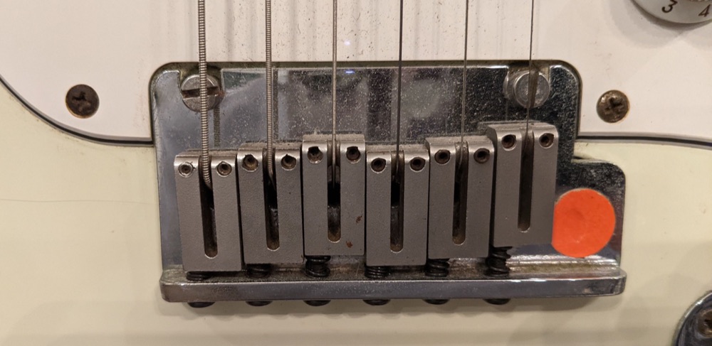
Tremolo bridges are anchored at a pivot point and are connected to springs that counterbalance the tension of the strings. When a tremolo arm (aka “whammy bar”) is connected to the bridge and is moved, the tension on the strings changes, varying the pitch(es) produced. Hardtail bridges are usually more consistent in tuning and tone. Bridges, tailpieces, and saddles are often made of metal for durability and stability. There are many different designs for and configurations of these parts; the preceding gives a sense of their basic function.
After a string is fixed at one end, it extends across the body of the instrument to a nut (made from metal, wood, or plastic) that suspendeds the string in air to vibrate freely. Slots or grooves in the nut keep the string in place as it is played. One issue to consider is what string gauges are going to be used in a particular slot, given string diameters can vary. Musical requirements will help determine how pitch ranges will map onto an instrument, which can subsequently be used to define string gauges and nut slot widths.
The final necessary component is a device that fixes the string in place at its other end, allowing the string’s tension to be varied to produce different tunings. Typical methods involve tuning pins, pegs, and machines.
Tuning pegs are a relatively simple option used in many instruments, such as those in the violin family. A tuning peg is a tapered cylinder to which a string is secured (often the string is threaded through a hole in the peg and then wrapped around the cylinder). Turning the peg increases or decreases the tension on the string, depending on the direction it is turned. The peg is pushed into a hole in the body / headstock / pegbox of the instrument until friction holds it in place (Figure 1.16). The advantage of this method is that it is simple: it requires few parts, which reduces both complexity and cost. The disadvantage is that pegs can allow slippage, which can contribute to intonation issues. It can also be difficult to precisely tune some types of strings using only a peg; therefore, fine tuners are sometimes needed.

Tuning pins are similar to tuning pegs and are seen in pianos, harps, and zithers. A piano tuning pin is a metal cylinder with a threaded bottom and flat edges on the top, making it easier to turn with a wrench. Like a peg, a string is threaded through a hole in the center of the pin and then wrapped around it. The pin is inserted into a pinblock, which is often several sheets of wood glued together. Angled holes are drilled in the pinblock, with a diameter slightly smaller than the pins, to help secure the pins in place (Figure 1.17).

Like pegs, the advantage of tuning pins is their relative simplicity. A disadvantage of pins is that over time, the holes in the pinblock wear due to the contact with the pins, providing a less secure connection. This issue can be addressed by using larger pins, applying a compound to the holes in the pinblock, or replacing the pinblock.
A popular alternative to pegs and pins is a mechanical tuning machine (or machine head) as featured on guitars and basses. These devices consist of a tuning post (capstan), a knob mounted on a shaft, and a worm gear that connects the two. The string is inserted through a hole in one side of the capstan and wrapped around the cylinder. On the other side of the capstan is the worm wheel. The shaft connected to the knob is threaded, making a worm that is mated to the wheel (Figure 1.18).

Tuning machines allow fine-tuning of a string. The ratio of the worm gear (usually around 14:1) balances the physical input needed to turn the knob and the resulting pitch change. At the same time, it provides a secure fixed end for the string as the worm drive cannot be backdriven due to the slope of its teeth. After the knob has been turned, the tension on the string forces the teeth to lock, stabilizing the gear’s (and string’s) position (see The Mechanical section for more information about gears).
While the preceding are the most common devices for tuning a string, there are other possibilities. One suggested by Bart Hopkin (1996) involves looping a string through an anchor (such as a washer) and then twisting the two string strands together. Changing the tuning of the string requires rotating the anchor, which affects how much the strands are twisted, which changes the pitch produced. This approach thus allows fine-tuning but at the same time is simple and cost effective.
An acoustic instrument requires some way to reinforce and amplify the vibrations of the strings, which do not project much sound on their own. For string instruments, methods of sonic projection typically involve acoustic resonators, radiators, and electric amplification.
The natural frequencies of a resonator respond to a driver’s oscillations; a radiating surface can project input frequencies. A common radiating surface is a soundboard, a sheet of material driven by a bridge coupled to a string. The greater the surface area of the soundboard, the more air it will move, producing greater sound (the soundboard of a piano is much larger than that of an acoustic guitar). The surface area of a soundboard also affects the range of frequencies it can produce, with larger soundboards capable of producing longer-wavelength, lower-frequency sounds (e.g., the bass response of a smaller upright piano is less than that of a larger concert grand). The natural frequencies of the soundboard contribute to the instrument’s timbral character. The best soundboards have a balance between rigidity and flexibility. If they are too massive or rigid, the driver (e.g., string / bridge) will not be able to adequately excite the soundboard. If they are too light or flaccid, the driver’s energy dissipates too quickly.
Other methods to acoustically amplify the sound of string instruments include membranes and acoustic horns. Membranes (e.g., balloons) typically produce a louder, shorter sound that emphasizes mid and high frequencies, depending on the size of the membrane. Acoustic horns are tapered devices that match the impedance between a sound source and air, amplifying input sound (they can also be used in the other direction, as in early recording devices). Martin Riches’s String Thing features an acoustic horn (Figure 1.19). Membranes and acoustic horns have been combined, as in the Stroh violin.

Resonators usually involve an enclosure, or sound chamber, of some kind. A sound chamber enhances an instrument’s bass response by exciting the air within the enclosure. This provides better bass response with smaller soundboards (e.g., double bass). Enclosures also help mitigate out-of-phase waves generated by the back of a soundboard. As the top of a soundboard compresses air molecules, the bottom of the soundboard creates an area of relatively lower pressure. As the soundboard oscillates, the waves that are created from the two sides of the soundboard are out of phase, leading to destructive interference that inhibits the sound. A structure in which the bottom of the soundboard faces into the enclosure is one way to mitigate these out-of-phase waves, but the lack of airflow can limit the soundboard’s movement. A compromise is to cut holes in the soundboard (such as the f-holes in a violin) that allow airflow in and out of the enclosure. The mixture of resonances, reinforcements, and interferences (enhanced by the fact that soundboards move in complex ways and not just back and forth) defines the timbral and dynamic character of the instrument.
Making a sound chamber can be a subtractive or an additive process. One method involves starting with an existing object (such as a gourd or a block of aluminum) and removing material (e.g., hollowing it out and finishing the inside, milling a shape with a CNC machine) to realize the desired cavity. Alternatively, parts (e.g., the soundboard or side pieces) can be joined (usually by adhesive) to create an enclosure. Struts and other reinforcing parts are sometimes needed to provide stability and to distribute vibrations to other parts of the enclosure.
Resonators and sound chambers can be made from a variety of materials. Wood has been used successfully and widely for string instrument resonators: spruce, cedar, and redwood are particularly popular choices (salvage wherever possible!). Metal can also be used to make soundboards or sound chambers that offer their own unique timbral characteristics. In general, there is not as much damping in metal resonators as in wood ones, which has implications on frequency response and sustain. Possible metals and metal alloys include aluminum, steel, copper, and pewter. Metal has been used to make conventional designs of instruments such as guitars (Bacon, 2021) and violins (Wilson, n.d.), and has also been used in the innovation of new designs, such as the resonator guitar / Dobro (developed by John Dopyera and colleagues in the 1920s). Many other materials that meet the requirements for rigidity and flexibility are possible, including Styrofoam (composer Lou Bunk has featured this material in his works), gourds (as seen in African, Indian, and Middle Eastern instruments), plastic, and synthetic materials. The development and proliferation of rapid prototyping technologies such as 3D printing have resulted in a panoply of examples of string instrument resonators made from scratch.
The timbral character and volume of a string instrument can also be manipulated through electric means. Electrical amplification provides an enormous dynamic range that can suit a small living room or a football stadium. Different combinations of signal processors, amplifiers, and speakers produce a variety of timbral effects. Electric amplification starts with transduction of the acoustical energy of the instrument, which can be effected by microphones, electromagnetic pickups, piezoelectric elements, optocouplers, and Hall effect sensors.
One way to convert an acoustic signal into an electric one is to place a microphone near the sound source. Michrophones are better suited for some musical scenarios than others. They are well-matched with acoustic resonators / radiators that can reasonably project on their own. While different microphone polar patterns can provide directionality, microphones often don’t provide the isolation desired. They are susceptible to feedback if oriented toward speakers projecting their output (i.e., live sound); therefore, they must be configured (in terms of position and gain) carefully. Mics require lots of other equipment including stands, cables, preamplifiers, and so on, which takes time and effort to set up, take down, and transport, and costs money (in addition to the cost of the microphones themselves).
Alternatively, transduction can occur “internally” with devices such as electromagnetic pickups. These devices consist of a magnet wrapped in a coil of wire (usually with thousands of turns), producing a magnetic field. As a ferromagnetic string vibrates, the magnetic field changes, inducing a current in the pickup coil. This electrical signal (which is quite small, on the order of a couple of hundred millivolts) is output to amplifiers and other signal processors. Electromagnetic pickups can be noisy as the magnetic coils are sensitive to electromagnetic interference (EMI) and radio frequency (RF) noise from mains wiring, computer screens, cell phones, and so on. An ingenious solution to this problem is the humbucking pickup, which pairs two coils with magnets facing in opposite directions, connected out of phase. When the two outputs are summed, the signals reinforce each other while the noise cancels out.
Piezoelectric elements are another means of transducing acoustic vibrations into an electric signal. Piezoelectric transducers (which can act as both sensors and actuators) consist of a thin layer of piezoelectric material (e.g., crystal, ceramic, polymer) bonded to a mechanical intermediary, such as a brass disc or film (Figure 1.20). When force is exerted on the piezoelectric material, an electric charge proportional to that force is generated over the faces of the crystal and is collected by the metal disc in the form of voltage that drives an electric current out of the attached leads. When the disc (or film) is coupled to an instrument, the vibrations of the instrument’s body deform the sensor and produce an analogous signal that can be amplified and processed. Piezoelectric transducers offer fast transient response, high output, and are cheap and easy to work with. Depending on how they are manufactured, piezo discs can exhibit strong resonant frequencies, and electrical impedance can be an issue, contributing to a characteristic “tinny” sound (see Mudhar, 2014, for further discussion). Drawbacks notwithstanding, piezo transducers offer a viable alternative to microphones.

Optical systems are another option. The basic idea is that one device produces light (LED, ultraviolet, etc.) directed at a light-sensitive receiver (photoresistor, photodiode, phototransistor, photo-SCR, etc.). When a string vibrates between these two devices, varying amounts of light pass from the source to the sensor (Figure 1.21). The sensor, when incorporated into a circuit, produces electrical variations that are analogous to the string’s vibrations. Connecting this signal to the analog inputs of a microcontroller allows the frequency of the vibrations (i.e., of the string) to be calculated.

Optical pickups have advantages over other methods. They are not affected by EMI and RF noise the way electromagnetic pickups are. They allow individual strings to be isolated, which can be useful (and sometimes necessary) when determining individual fundamental frequencies or processing different strings with different signal chains (imagine chorus on some strings and delay on others). The disadvantages of optical pickups are that they require precise alignment and that ambient light can introduce noise into the signal. Recent advances in optical pickups involve sensors that detect reflected light and incorporate filtering approaches to mitigate these issues (Haddad, 2015).
Hall effect sensors are a more recent innovation in the world of string pickups, though their history may be older than some think (see Iodice, 1978). Hall effect sensors transduce changes in a magnetic field into electrical signals according to the Hall effect. The Hall effect occurs when an electric current flows through a magnetic field perpendicular to that current. The magnetic field exerts a force on the charges, moving them to one side of the conductor. Changing the direction of the electrical current or magnetic field affects the accumulation of charge, as seen in Figure 1.22. The accumulation of charge on one side of the conductor produces a voltage difference relative to the other side.

A Hall effect sensor consists of a semiconductor material connected to an electric circuit proximate to a magnet whose flux lines are perpendicular to the current flow. The sensor measures the magnetic field strength, which depends on the circuit’s proximity to the magnet. Placing a vibrating ferromagnetic string within this magnetic field creates an analogous change in voltage; acoustic energy is transduced into an electric signal. An early design for a pickup using this principle was patented by Robert Iodice (1980).
Because their output signals can be amplified, electric string instruments do not require the same large resonant bodies as their acoustic counterparts (though such bodies are still of interest due to their timbral contributions). The bodies of electric string instruments, therefore, can be smaller, which has benefits in terms of design and fabrication complexity, transportability, and cost. GuitarBot, PAM, and Swivel are examples of relatively minimal bodies that use electrical amplification.
The acoustic / electric divide comes with strong opinions that have musical implications. Strings are some of the oldest bearers of our musical traditions, with acoustic instruments such as the violin family and the sitar defining the character of musical expressions and cultures. Amplifying an acoustic instrument transforms its sonic identity and opens up a vast world of possible musical manipulations. The electric guitar has inhered in our musical culture to a point where it is viewed through a lens previously reserved for acoustic instruments. It is characterized by signature timbres, idiomatic techniques, and musical styles, like its acoustic counterparts. It stands in distinction to other kinds of musical technologies, like the synthesizer, which will perhaps have to wait for similar perspectival transformations. This social context is in play for the designer of a robotic string instrument that may be acoustic, electric, or some combination of the two.

Aerophones can be made from a variety of materials, including wood, metal, ceramics, plastic, glass, and bamboo (woodwinds are not always made of wood!). The part you are making and the fabrication methods available are primary factors in choosing materials. For example, when making the bore of an aerophone, it is usually easier to buy a prefabricated PVC tube from a hardware store than to drill one from a block of wood. With that said, it is possible to make daunting processes easier, such as breaking a shape into parts and then joining them. Smaller components with tight tolerances might be best realized using tools such as 3D printers; thus, prototypes will likely contain a solid dose of plastic. The process is iterative, so it is best to prototype in an inexpensive, easy-to-work-with material. Once you feel confident in the design, use the material that best suits your visual and sonic goals.
There are general principles to keep in mind when making your own edge-blown aerophone. The larger the blowhole area, the higher the pitch. A blowhole with a width of about ½ inch is suitable for a middle-range flute. Short, wide openings produce a clear tone, and when the air flow rate increases, they tend to produce a pitch an octave above as opposed to a pitch glide. Long, narrow openings produce a “breathier” sound, and when the air flow rate increases, they tend to produce pitch glides rather than jumping octaves (Hopkin, 1996). Oval shapes for blowholes are better than circular ones as they provide a wider, flatter edge for the air beam to interact with. Perusing the work of instrument builders provides many variations on these ideas, such as the “two semicircles” or “rounded rectangle” shapes (Irish Flutes—Heads and Barrels, n.d.). Blown edges can be modified (rounded, beveled) to affect how tones are produced. Side-blown flute edges should be a bit less than 90°, while end-blown flutes can be 25–45°. Fipple windways should be as wide as the edge, short (< 2 mm), smooth, and positioned so that the air meets the edge directly. Given the precise dimensioning needed in fipple design, 3D printing is a good way to start. If you want to get your hands dirty, you can make a fipple yourself out of common materials such as copper pipe and wooden dowels (see Fulton-Bennett, n.d., for a tutorial).
The practice of mouthpiece and reed design has been refined over many years; thus, acquiring these objects off the shelf is generally your best bet (particularly for double reeds). For those adventurous types who are for scratch or nothing, it is possible to make your own reeds, such as out of a curved strip of metal. An idioglottal reed is one that is part of the body of the instrument (think of it as a “built-in” reed) that is defined by three perpendicular beveled cuts in the tube, leaving the reed attached at one end (Figure 1.24). The reed needs to be able to beat against the walls of the tube, which can be achieved by removing enough material in the cuts or bending the reed out slightly (bamboo accommodates this design).

Another possibility is to cut the end of a tube at an angle of 15–30°. Sand the cut so that it is smooth and remove a bit more material at the tip so that there will be an opening for the reed to beat against. Fine-tune the tip opening and couple the reed to the tube using a hose clamp, zip tie, or even a rubber band (Figure 1.25).

Membrane aerophones are usually realized via rummage or built from scratch. The key is to find the right material for the membrane that also contains an opening for the input air stream. Balloons are a contender, given their design and availability, though most are not particularly durable. Other kinds of synthetic elastomers may also work. The other main part needed is a way to secure the membrane to the tube, which could be accomplished with rubber bands, zip ties, Velcro strips, or hose clamps.
Free reeds are more commonly found and are more tedious in tuning, so acquiring these from an existing instrument (such as a harmonium or accordion) is likely the path of least resistance. For the DIYers, making a free reed requires a strip of flat, springy material (usually brass or stainless steel) that isn’t too massive. Secure the reed on one end of an opening that accommodates the reed’s vibration and provides enough closure to produce pulses of air (Figure 1.26). The reed is usually set on top of the opening, with a slight bend to allow some space at rest. The frequency of the reed’s vibration depends on the mass of the portion that swings and the rigidity of the portion that flexes. Increasing mass to the portion that swings by adding material to the end of the reed or lengthening it will lower the pitch; reducing mass by thinning the end of the reed or shortening it will raise the pitch. Thinning the reed near the base where there is a lot of flex will lower the pitch while more rigidity at the base will raise the pitch.

Corrugaphones are a more recent phenomenon that consist of readily available materials, so they are best made from scratch. Corrugated pipe is typically used for drainage applications and can be found at your local hardware store. The pitch range of the pipe is determined more by diameter than length, with larger diameters producing lower notes. The length of the tubing will determine how many of the harmonics can be produced, with longer lengths facilitating lower harmonics. Corrugaphones are an interesting possibility for musical machines as the high air flow rates are achievable via mechanical pumps, and the rate of air flow can be precisely controlled using pressure regulators. Multiple tubes can be combined in a single instrument (see Hopkin, 1996). Mechanized valves on these tubes would allow you to sound melodic lines or dense chords. A group of my students made an ensemble of mechanized whirly tubes; the sonic product was ethereal and highly engaging (Jandus et al., 2023).
Mouthpieces for lip-buzzed instruments vary in shape and size and have benefited from extended periods of development in the hands of experienced instrument makers. For these reasons, acquiring a mouthpiece off the shelf is likely best. If you want to try making one yourself, look at existing mouthpieces for inspiration; Figure 1.27 features a few examples. Wood, plastic, clay, and metal are possible materials to work with. Given the geometries involved, such a part could be fabricated using rapid prototyping technologies, such as 3D printing. This would enable you to experiment with different designs and different materials.

Making a percussive aerophone involves a resonator (covered below) and a beater that strikes it. Beater material should have a balance of rigidity and flexibility, with some padding to attenuate sound at contact with the enclosure. Rubber or foam flip-flops or flooring tiles work well (the latter are used in the MPR Lab’s Percussive Aerophone; Sundberg et al., 2018) as they are easy to cut and shape and excite the air column effectively without coloring the sound exorbitantly from idiophonic contact. Enclosures can also be struck or scraped on their sides, the latter made possible by a series of ridges. Instead of being hit by another object, the tube can be the hitter, striking surfaces such as the ground to transform into a musical object. The potential of such stamping tubes, used in cultures throughout the world, can be revealed the next time you come across a cardboard tube (such as the kind that holds posters). Sound quality varies widely, so experiment. The ease of playing tubes in this way may inspire some machinic builders; be aware that structures and mechanisms required to do so may be more involved than a design where the tubes are stationary, and the beaters are moved.
As previously mentioned, musical sirens typically involve spinning discs that contain evenly spaced holes. The design problem then becomes determining the disc’s size, the number of holes it contains, and its rotational speed. One strategy is to feature numerous concentric circles of holes on the same disc, with each circle having a different number of holes corresponding to different pitches, given the same rotational speed of the disc. The precise configuration of holes is determined by the pitch set desired by the builder. The MPR Lab’s Parthenope (Sidler et al., 2020) takes this approach, featuring two discs, each with four concentric circles of holes. A disc with 11, 12, 14, and 15 holes yields a range of five semitones in the pitch interval pattern W W ½. A second disc with the same hole configuration but offset by seven semitones relative to the lowest pitch of the first disc completes the diatonic scale. Alternatively, two discs that each have the hole patterns 1, 2, 4, and 8, offset from each other by 48 semitones, span a range of eight octaves. Producing intermediary pitches in any of these configurations is then a matter of changing the rotational speed of the discs. The air nozzles should be positioned close to the discs, and different nozzle sizes produce different dynamic levels (Parthenope uses diameters of 0.2, 0.6, and 1.0 mm).
For potters, glass-blowers, and other such artisans, making globular vessels from scratch is a realistic and potentially sonically rewarding possibility. Manufacturing and prototyping processes such as 3D printing also may yield usable results, though the size and materials used will be a factor. For the majority of us, globular vessels of musical value are most easily acquired through rummage. Our homes are filled with all sorts of interesting chambers that enclose volumes of air with musical potential. The volumes of these containers can be modified by adding material such as water or sand (the former is how musical wine glasses are tuned). This was the inspiration behind the MPR Lab’s WAT-R, which uses a set of glass conical separatory funnels (think chemistry lab) that fill and empty automatically, containing different amounts of water through a series of solenoid-controlled valves to create a variety of pitches (Figure 1.28).

Tube resonators can be acquired off the shelf or through rummage, but they are particularly attractive to makers of musical machines because they are reasonably made from scratch. The latter involves figuring out the volume of air they will contain, which will affect the pitch and harmonic spectra they produce. A cylindrical tube open at both ends will enclose ½ the wavelength of the fundamental mode of vibration. Conical tubes behave similarly. A cylindrical tube open at one end (e.g., some organ pipes and clarinets) encloses ¼ of the wavelength of the fundamental mode of vibration. Practically, this means that a tube with one closed end will produce a pitch an octave lower than a tube of the same length that is open at both ends.
The tube lengths needed to produce a desired set of frequencies can be calculated. The modes of vibration for the previously mentioned shapes can be determined using the formulas in Table 1.2. The frequency of vibration of a particular node is related to the speed of sound and the length of the tube. The general formula is given first, followed by an illustration for the first mode of vibration for these different cases, where f = frequency, v = the speed of sound (343.5 m/sec or 1127 ft/sec), L = tube length (meters), and n = mode number.
| Cylinder open both ends / cone | Cylinder open one end | |
|---|---|---|
| General formula | f = nv/2L, L = nv/2f | f = (2n−1)v/4L, L = (2n−1)v/4f |
| Mode 1 | f = v/2L, L = v/2f | f = v/4L, L = v/4f |
Determine the frequency you want and plug it into the equation to determine the tube length. For example, for a cylinder open at both ends, to produce 440 Hz (A4):
Alternatively, tube lengths could be determined proportionally. Start with a tube length that is a reference from which you can calculate the other lengths according to the temperament you wish to use. If you want to produce 12-tone equal temperament, the ratio between adjacent pitches is the twelfth root of two:
You can use this value in combination with the equations in Table 1.2 to determine the appropriate tube length. For example, say you start with a tube open on both ends that is 39 cm long that produces the frequency 440 Hz (A4). To find the tube length that would produce A♯4, first determine the frequency (f) of the pitch:
Plug this number into the formula in Table 1.2 to find the tube length:
As a shortcut, you could multiply or divide the reference tube length by 12√2 to find the length that produces a semitone lower or higher, respectively. If you want to use another temperament such as just intonation, use ratios of the reference tube length to produce the desired intervals. For example, in just intonation, a tube length in the proportion 1:2 would produce a pitch an octave higher, 4:5 a major third, and so on. If manual calculations are not your thing, charts and calculators are plentifully available online (at least you now know the logic behind the mathematics).
The design of a tube or vessel will affect the sound’s dynamics and timbre. Conical tubes project better with larger openings; flaring the end is one commonly employed option. Longer, skinnier tubes generally produce more prominent overtones. The proportions of length and width can thus be adjusted to create different timbral effects. As long as the proper cross-sectional area is maintained, gentle curves in the tube (i.e., no kinks) shouldn’t affect the sound too much.
Manufacturing resonators is achievable for most, but the process can be tedious. Resonators can be made from a variety of readily available materials. Copper or PVC pipes found in hardware stores, plastic beverage bottles, and jugs can all work well. The calculations above are guidelines, as objects in the real world typically behave differently than abstract ideals because of a host of complicating factors such as the extension of standing waves and wall rigidity. In the case of tube making, this means erring on the side of lengths slightly longer than ideal: it is easier to file down than to add back. Test the pitch produced with a tuner and gradually reduce the material as needed. Repeat. Particulate matter is generally not something you want to inhale, so wear respiratory protection when doing so.
Some tube aerophones (such as flutes) require a stopper at one end. These can be made from cork, such as from wine bottles. For a side-blown flute, the distance from the stopper to the center of the blowhole should be roughly the internal diameter of the tube, which affects tone quality. For an end-blown flute, the stopper is placed at the far end of the tube. Stoppers are most useful when adjustable, allowing intonation to be set properly. Bart Hopkin (1996) suggests using weather-stripping wrapped around a double-headed nail. The shaft of the nail protrudes out of the tube, allowing for the stopper, and thus the pitch produced by the pipe, to be adjusted.
Perhaps the simplest way to change pitch on an aerophone is to vary airflow to produce different partials of the tube’s harmonic series. All that is needed is a tube that is long enough to produce ½ the wavelength of the fundamental mode of vibration. The difficulty of this approach is that the musical capabilities of the system are then largely a function of the air supply and regulation systems.
Another way to produce different pitches is to have one sonic object (e.g., free reed, tube) per pitch, as in an organ or harmonium. This simple / distributed approach is advantageous because it uses a straightforward method applied many times, but collectively, there may be implications regarding space, cost, and configuration.
An intermediary approach, in which a single tube can produce different pitches, can be realized by using toneholes to vary the effective vibrating length of an air column. Tonehole size and location both affect the pitch. A tonehole whose diameter is the same as that of the tube acts as an effective tube endpoint. Enlarging the holes raises the pitch, while making them smaller (e.g., by using autobody filler or epoxy) lowers the pitch. Larger toneholes allow for greater volume and more upper partials. Tonehole placement is difficult to calculate exactly, given the number of factors in play, such as the size and thickness of the hole as well as the number of toneholes that are open or closed relative to the open hole. One approach is to figure out the tube length that corresponds to the desired frequency as described above. Adjust the hole location according to the following factors:
- If the hole is smaller than the diameter of the tube, is significantly thick, or there are many closed toneholes above the open hole (all of which lower the pitch), move the hole toward the mouthpiece (which raises the pitch).
- If there are additional open toneholes below the open tonehole (which raises the pitch), move the open hole away from the mouthpiece (which lowers the pitch).
If making from scratch, toneholes need not be drilled to accommodate human fingers. A straight line of holes is one option that would make configuring “fingering” mechanisms easier, but sonically, the holes do not need to be oriented linearly. Spacing the holes around the circumference of the instrument could create some interesting visual designs. The position of toneholes on a globular chamber doesn’t significantly affect sound production.
Register holes, when open, allow aerophones to sound pitches in higher ranges. They do this by inhibiting the lowest mode of vibration by creating a leak at a point where pressure accumulation is required for that mode to oscillate. At the same time, the register hole should not affect the upper modes of vibration. It follows that register holes should be placed at a node of the mode you want to sound, such as the second, while at a point of maximum pressure variation of one you want to attenuate, such as the first. Whether other toneholes are open will affect the position of these nodes, so a compromise must be made to account for the different pitch possibilities. Position the register hole for a pitch in the middle of the instrument’s range. This will be more toward the mouthpiece than the ideal location for the entire tube, but it will accommodate the range of pitches that the instrument can produce.
The effective vibrating length of an air column can also be varied with valves and slides. Valves are mechanisms that act as switches, routing air flow to an extended portion of tubing when activated, producing a lower pitch (Figure 1.29).

They are typically used to connect a single length of tubing, but they can also be used to route airflow to multiple tubing lengths to create different pitches. Valves are difficult to manufacture, so they are best acquired off the shelf or through rummage.
A slide involves a stopper at the end of a rod that can be moved in the tube (e.g., a slide whistle) or open-tube slides, such as those found in trombones. Slide whistles are a compelling candidate for musical machines because proper intonation requires precise positioning that is typically difficult for human players but well within the capabilities of a motor enhanced with position feedback. Line the circumference of the stopper with a rubber gasket and lubricate the interior of the tube to allow for fluid motion. Tube length in open-tube slides is typically varied by using telescoping sections. The problem is that two telescoping sections extend to a length less than twice their retracted length, corresponding to a pitch range slightly less than an octave. More telescoping sections would mean longer tube lengths, resulting in a greater pitch range. At some point, these may be impractical for humans to play, but such designs are a good candidate for machinic actuation. The visual of multiple tubes, each with many telescoping sections, could be interesting. Fabricating such a system would require tight tolerances to avoid air leakage and reduced friction between tube sections to enable rapid, quiet translation. A WPI student group recently explored these ideas in Sliding Harmonic Tubes (Weber et al., 2024), demonstrating the potential of this approach.
Hopkin (1996) describes magstrips as a pitch control method that is a compelling possibility for a musical machine. The idea is a steel tube with a slit (½″ or less) down its length, almost to the mouthpiece. A magnetic strip is fixed to one end of the slit, extending diagonally to a point where it is secured to a structure perpendicular to the tube. A finger moves along the strip, pressing it down against the slit, changing the effective vibrating length of the tube. While Hopkin’s design was intended to be played by humans, a machinic version of the instrument could feature a linear actuator or a belt-pulley system that moves an artificial “finger” along the tube’s length. Because the strip and the tubing are magnetically attracted, a tight seal is achieved (Figure 1.30).

The approaches mentioned above can be mixed and matched, even if such combinations are not common in the instruments we know. For example, toneholes can be added to the tubes or vessels of a percussive aerophone to extend the range of pitches that they can produce, a practice used by musicians and builders such as Darrell De Vore (Hopkin, 1996). The ideas presented here can be thought of in a modular way. Experiment by combining them. The capabilities of machinic actuation add a new dimension to such experiments. Who knows, maybe you will come across a musically inspiring configuration that has yet to be heard!
For those who seek to delve further, consult the following resources:
- Bart Hopkin’s Musical Instrument Design (1996) — a classic from which many of the ideas in this primer were learned.
- Fletcher, N. H., & Rossing, T. (2012). The physics of musical instruments. Springer Science & Business Media.
- Anatomy of a conga: Know your conga drum brand. (n.d.). Remo. Retrieved July 1, 2020, from remo.com/support/faq/anatomy-of-a-conga-drum
- Animal skins vs. synthetic world percussion heads. (n.d.). Remo: Support. Retrieved March 14, 2020, from support.remo.com
- Azzarto, F. (2015a, February 9). What you need to know about … drum shells. Modern Drummer Magazine.
- Azzarto, F. (2015b, March 11). What you need to know about … counterhoops. Modern Drummer Magazine.
- Bacon, T. (2021, February 18). Metal machine music: The history of guitars made from metal. Guitar.com | All Things Guitar. guitar.com
- Barton, S. (2021, April 27). Mechanophore (2021)—Scott Barton [Video recording]. youtube.com/watch?v=0F9326b7rLs
- Deep-Reach Expansion Plugs. (n.d.). McMaster-Carr. Retrieved March 2, 2020, from mcmaster.com
- Fulton-Bennett, K. (n.d.). Copper pennywhistle. Retrieved June 17, 2022, from scribd.com/document/996098678
- Fundamentals of the kalimba—Kalimba magic. (n.d.). Retrieved March 21, 2020, from kalimbamagic.com/info/how-to-play/fundamentals-of-the-kalimba
- Haddad, W. S. (2015). Optical instrument pickup (United States Patent US9082383B2). patents.google.com/patent/US9082383B2
- Hopkin, B. (1996). Musical instrument design. See Sharp Press.
- Iodice, R. M. (1978, November 1). Hall effect pickup for stringed musical instruments. Audio Engineering Society Convention 61.
- Iodice, R. M. (1980). Coil-less magnetic pickup for stringed instrument (Patent US4182213 A).
- Irish Flutes—Heads and Barrels. (n.d.). Retrieved June 17, 2022, from mcgee-flutes.com
- Jandus, J., Pena_Stein, D., Siegall, K., & Trilling, E. (2023, December 17). Whirly tunes | Musical Machines Gallery. Musical Machines Gallery. wp.wpi.edu/musicalmachines
- La Favre, J. (2007). Tuning the marimba bar and resonator. lafavre.us/tuning-marimba.htm
- More about StringThing. (n.d.). Retrieved July 22, 2021, from martinriches.de/stringmore.html
- Mudhar, R. (2014, October 3). Using piezo contact mics right. richardmudhar.com
- Saragosa, W. A. (2009). Kalimba system (United States Patent US20090217802A1). patents.google.com/patent/US20090217802
- Sidler, M., Bisson, M., Grotz, J., & Barton, S. (2020). Parthenope: A robotic musical siren. Proceedings of the International Conference on New Interfaces for Musical Expression, 297–300.
- Sundberg, K., Barton, S., Walter, A., Sane, T., Baker, L., & O’Brien, A. (2018). A Robotic Percussive Aerophone. Proceedings of the 18th International Conference on New Interfaces for Musical Expression, 409.
- Violin soundpost: The soul of the instrument. (2021, October 7). Violinspiration. violinspiration.com/violin-soundpost
- Weber, O., Obert, S., Schwarz, J., & Cloutier, M. (2024, December 18). Sliding harmonic tubes | Musical Machines Gallery. Musical Machines Gallery. wp.wpi.edu/musicalmachines
- Wilson, P. (n.d.). Metal fiddles. Pamela’s musical and other activities. Retrieved December 17, 2021, from pamelasmusic.co.uk